Bulletin 85: Tank Sampling Device

New and Improved Tank Sampling Device

Take a sample from the bottom surface, or any level, of an underground tank, barge, or tanker cargo tank for inspection

The new version of this product has been designed so that the cover will fit a Mason jar as well as a bottle. The stopper will fit any drink bottle or common gallon jug.

Proper housekeeping of a tank farm requires that management knows the conditions of tank bottom accumulations. Is there a water bottom? What color – clear, brown, black? Is there any scum or obvious microorganism material?

The importance of knowing that the settled water in the sump of a storage tank is discolored cannot be overstated. After all, the coloration of the water is caused by contamination of the fuel itself. So when dark-colored water is found, it should be removed and the fuel should be checked using the color rating of filter membranes (ASTM D2276).

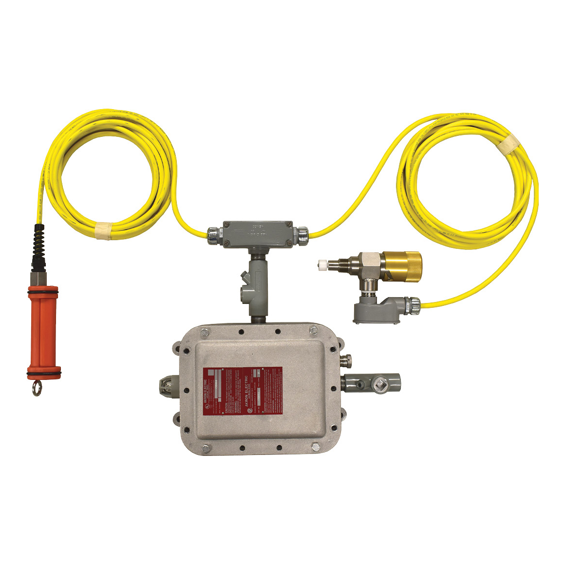
GTP-9670-20 (pictured above) combines a threaded cap that will fit a standard Mason jar (sold separately) with 20 feet of weighted, bonded polyurethane tubing. Simply lower the weighted end of the tubing to the desired level and operate the plunger pump to draw the sample. The assembly comes complete with internal bonding and grounding wire and clamp.

Every pump comes with both a jar connection and a conical stopper, designed to seal on the opening on a bottle or container with a 0.70-1.10” inside diameter.

How to Order

GTP-9670
pump with 10 or 20 feet of hose

GTP-2811
16oz glass jar

GTP-8649-2
replacement 20′ hose with fittings

Bulletin 85: Tank Sampling Device2025-05-01T13:55:49-04:00

Bulletin 84: Hydrant Pit Shut-Off Valve

Refueling Hydrant Pit Shut-Off Valves

Overview

One thing is true of all hydrant pit control valves, and that is that they occasionally leak and/or need service. To stop the leak or service the valve without depressurizing the hydrant system, or a portion of it, a manual shut-off valve must be located between the hydrant pipe connection and the hydrant pit control valve.

Shut-off valves are sized either 4×4”, 6×4”, or 6×6” depending on the hydrant pipe size and the connection size of the hydrant pit control valve. The shut-off valve cannot be a “wafer” style valve; it must be flanged on the inlet and outlet. By using a flanged-type under-hydrant valve, the entire hydrant pit control valve can be removed, if necessary, and no leakage will occur.

A shut-off valve may be a flapper-type or butterfly-type. The butterfly-type is good, but the disk remains in the flow path when the valve is open and acts as a restriction. The flapper-type is excellent on pressure drop, but a plain flapper cannot be opened against pressure. For this reason, our valve incorporates a “valve within a valve,” which automatically equalizes pressure when you start to move the operating handle. It is very easy to operate, yet provides all the advantages of a flapper-type valve. Other flapper-type designs rely on a separate tiny, vulnerable, manually operated valve for equalizing pressure. This is inconvenient, and it may also be accidentally left open.

The unique feature of the Gammon Under-Hydrant Shut-Off Valve is that, in addition to providing the standard shut-off feature, it can protect the airport and personnel from a disastrous fire because it closes automatically as soon as the temperature reaches 165°F (74°C). A fusible link in the chain that normally holds the valve open will melt at this temperature, resulting in instantaneous closure.

Under normal conditions, the valve can be closed easily by unhooking the chain. This action is totally independent of the fusible link. Unless the fusible link melts in a fire, it will never need to be replaced.

We usually refer to our Under-Hydrant Shut-Off Valve as an “Emergency Valve” because it will function in an emergency situation, which is usually more important to the approval authority than the basic shut-off feature. For any customer who does not need this added safety feature, we do not include the fusible link. Our valve then serves only as a “service valve,” like any other valve.

View of Device Looking Upward from Beneath the Valve

Design Features

This valve has special features that were necessary to make it pass the API-6FA fire test. This test requires that leakage through the valve or outside the valve will not exceed specified amounts after the seals have burned away at a temperature of 1600°F. To meet those specifications, we were unable to seal the operating shaft with o-rings so we used a unique labyrinth-type seal assembly that has proven to be reliable in other products we make.

Opening Relief Feature

The primary advantage of this valve is its opening relief feature. Proven in many years of service on model GTP-2654, we made no changes when this feature was applied to model GTP-3978. In the closed position, the hydrant pressure assists the spring in keeping the valve tightly closed. Therefore, to open the valve, it is necessary to bleed fuel from the pressure side into the hydrant valve. To do this, the operator applies a small constant force (about 4-5 lbs.) to the handle. This force opens an internal bleed valve which passes fuel to the hydrant valve. When the pressure in the hydrant valve equals the hydrant system pressure, the operator can easily open the main valve and then attach the fusible link chain to arm it. A competitive valve on the market today has a separate, external bleed valve that can be opened by the operator who must reach under the hydrant valve to turn the handle. After the pressure equalizes, he must remember to close that valve.

OPENING RELIEF VALVE OPEN

Note cross-drilled holes for flow.

OPENING RELIEF VALVE CLOSED

General Information

Airport design engineers in many parts of the world are specifying the features of our Model GTP-3978-3 because they achieve two objectives that a plain butterfly valve (or even a fire-safe butterfly valve) does not offer. A non-fire-safe valve offers no leakage protection. A fire-safe butterfly valve is capable of stopping fuel flow in a fire only if it is in the closed position when a fire develops.

Clearly, an under-hydrant valve is expected to be in the open position except under unusual circumstances, such as for maintenance of the main hydrant control valve. Therefore, our valve is favored because it not only serves as a maintenance valve, but also will sense the presence of a fire and then close automatically to ensure that the fire will not be enhanced by more jet fuel.

Under such a condition, the fire may develop intense heat that will destroy all of the seals in any valve whether it is a butterfly or flapper-type. However, the unique design of our valve ensures that leakage will be minimized in accordance with API Bulletin 6FA even if the seals have been burned away.

In summary, our valves are in service at a number of airports worldwide, from New York’s JFK to Singapore’s Changi Airport. We have had virtually no replacement part orders, proving that these valves require no maintenance or replacement parts.

Our valves serve as manual shut-off valves and emergency valves. All working parts are solid stainless steel. They are very heavy duty. They offer almost no resistance to flow. Samples are available upon request. Once you have seen our valve and compared it with any and all alternatives, we are confident that you will agree no equal to our valve exists.

How to Order

Approximate weights: 4” x 4” 150 lb. flanges 51 lbs., 6” x 6” 300 lb. flanges 78 lbs., 4” x 6” 150 lb. flanges 47 lbs.

EXAMPLE: GTP-3978-23126 is an emergency valve as follows: 6” x 6” valve type, 150 lb. x 150 lb. flange rating, raised face flanges, stainless steel, with a valve height of 6 inches.

Bulletin 84: Hydrant Pit Shut-Off Valve2025-05-01T13:55:49-04:00

Bulletin 80: ASTM Color Standards

ASTM Color Rating Booklet

For use in color rating filter membranes for aviation turbine fuels
in accordance with Appendix X1 of ASTM Test Method D2276/IP216

Available through Gammon Technical Products distributors worldwide.

We are proud to have been appointed as the central custodian for this color standard booklet.

We supervise the manufacture and color certifications.

GTP-1074-1
standard color rating booklet

GTP-1074-AF
standard booklet, plus particle assessment guide

Specifications

Each color standard panel has been certified in accordance with the Munsell Color rating system to Triple A standards for chroma, value, and hue. The colors, as specified in ASTM D2276/IP216, are as follows:

Scale A

Rating
Number
Munsell CIELAB
L* a* b*
0 N 9.6 98.99 0.00 -0.01
1 2.5 YR 9.3/0.5 94.03 1.41 2.01
2 2.5 YR 9/1 91.08 2.69 3.79
3 2.5 YR 8.5/2 86.21 5.27 7.43
4 2.5 YR 8/3 81.35 8.90 12.37
5 2.5 YR 7/4 71.60 12.41 16.88
6 2.5 YR 6/3.4 61.70 11.07 14.37
7 2.5 YR 5/2.8 51.57 9.60 11.66
8 2.5 YR 4/2.2 41.22 8.50 9.60
9 2.5 YR 3/1.6 30.77 6.85 6.84
10 2.5 YR 2.5/1 25.61 4.48 3.83

Scale G

Rating
Number
Munsell CIELAB
L* a* b*
0 N 9.6/ 98.99 0.00 -0.01
1 N 9.3/ 94.03 0.00 -0.01
2 N 9/ 91.08 0.00 -0.01
3 N 8.5/ 86.21 0.00 -0.01
4 N 8/ 81.35 0.00 -0.01
5 N 7/ 71.60 0.00 -0.01
6 N 6/ 61.70 0.00 -0.01
7 N 5/ 51.57 0.00 0.00
8 N 4/ 41.22 0.00 0.00
9 N 3/ 30.77 0.00 0.00
10 N 2.5/ 25.61 0.00 0.00

Scale B

Rating
Number
Munsell CIELAB
L* a* b*
0 N 9.6/ 96.99 0.00 -0.01
1 5 Y 9.3/0.5 94.03 -0.60 4.21
2 3.4 Y 9/1 91.08 -0.70 8.05
3 1.7 Y 8.5/2 86.21 0.13 14.89
4 10 YR 8/3 81.35 2.78 19.60
5 10 YR 7/4 71.60 4.50 25.82
6 10 YR 6/3.4 61.70 4.28 21.57
7 10 YR 5/2.8 51.57 4.09 17.64
8 10 YR 4/2.2 41.22 3.60 14.46
9 10 YR 3/1.6 30.77 2.88 9.68
10 10 YR 2.5/1 25.61 1.96 5.76

Every color page is wire bound.

Each color standard has a 1 inch (25mm) window so that the membrane can be viewed for better accuracy in color rating.

Every color page has an index tab to speed up finding the right page.

Margins are provided at the ends of color pages to avoid fingerprints on color panels.

Fuel resistant lamination is provided on the back on each color page and on an interleaf between each color page. This prevents a wet membrane from soaking the page and possibly altering the color.

IMPORTANT NOTE: Instrumented tests have proven that some colors in the old, original booklets dated 1981 have changed over the years since they were originally manufactured. Those booklets have been declared invalid and must be destroyed.

ASTM D2276, paragraph X1.5.1.1 states the following:

Charts in use should be checked periodically against a reference set of color standards to eliminate the possibility that sunlight or soiling due to handling may have appreciably changed the colors. The reference set is a set of color standards obtained new, stored in dry, dark conditions, and is only used for the purpose of checking the standards in day-to-day use.

Bulletin 80: ASTM Color Standards2025-05-01T13:55:46-04:00

Bulletin 79: Aircraft Refueling Hose Tester

GTP-2157-A

The Gammon Aircraft Refueling Hose Tester is made of non-ferrous materials, designed for periodic testing of jet refueling hose, using jet fuel for pressurizing.

The unit consists of a 10 U.S. gallon (38 liter) aluminum tank (GTP-2234) equipped with a vented fill cap, hand pump (GTP-8076), 0-1000 psi 4.5” face pressure gauge (GTP-281-H), quick disconnect (GTP-992-4MA), and six feet of 1/4” hose (GTP-8079) to connect to the tester.

Hose Test Procedure

Overview

This tester is designed to perform integrity tests on hose assemblies used in the refueling of aircraft. A thorough inspection of the hose should be done before testing, and if any significant flaw is found, the test should not be run. The purpose of this test is to ensure that the couplings are still secure and that no physical flaw exists that cannot be seen on a physical inspection. AIR MUST NOT BE PRESENT in the system or else, in the event of a failure of the hose or a fitting, the trapped air will cause an explosive release carrying particles at high speed as it expands.

Procedure

The primary application of this tester is for testing aircraft refueling hose in accordance with API Bulletin 1529. When testing newly coupled Grade 1 hose, the test pressure is 300 psi. Periodic tests are required at the working pressure which is 150 psi. When testing Grade 2 hose, the test pressure is 600 psi for newly coupled or recoupled hose, and 300 psi for periodic testing. Because most aircraft refueling hose is Grade 2, the instructions below are written for a 300 psi periodic test with the hose full of jet fuel and remaining attached to the hose reel or to piping on the refueling vehicle.

When testing equipment other than hose, the standard practice is to perform hydrotests at 1.5 times the design or working pressure.

Note: If failure occurs during this test, fuel may be released. Be sure to have the site of the test in a secure area so that the spill will be contained and no fire hazard exists. Wear the proper personal protection such as eye protection.

  1. Extend the hose to its full length.
  2. Be sure that:
    • No air is present in the hose
    • The hose and couplings are fully inspected for flaws
    • The hose reel is rated for 300 psi proof pressure and there is a 300 psi rated isolation valve upstream
    • The overwing nozzle has been removed and a pipe cap with vent valve has been installed
    • The underwing nozzle can handle 300 psi (some brands cannot), and that it is connected to a fueling adapter with a 300 psi rated stop valve downstream. Open the nozzle valve before pressurizing the hose.
    • Any hose reel and/or nozzle that does not meet the 300 psi rating has been removed before testing. Install a pipe cap with a vent valve on the hose end.
    • The hose is marked all the way around at the edge of the ferrule/fitting with a light coat of paint or by any other means so that you will be able to clearly see if the hose begins to slip out of the ferrule when the hose is pressurized.
      Vent valves are used to released all air before pressurizing the hose.
  3. Close the hose reel inlet valve.
  4. Connect the supplied hose “A” to the quick disconnect “B” on the hose tester and then to the nozzle, or any other point. Underwing nozzles have a plug in the side which can be used for this purpose. Once again, be sure no air is present in the hose, nozzle, or associated pipe.
  5. Open valve “C” and step lightly on hose “A” to displace any air in it. Close valve “C.”
  6. Pump the pressure up to 300 psi in accordance with API-1529 Appendix D for Grade 2 hose, observing for leaks, bubbles, cuts, or blisters. Roll the hose to observe the entire surface. If defects that penetrate the cover material to the reinforcing cord are observed, stop the test; it is a failure. Depressurize immediately as instructed in Step 8 below.
  7. Look at the paint mark on the hose at the ferrule. If there is more than 1/32″ (0.8mm) gap after the test pressure has been released, the test is a failure; depressurize after the test.
  8. When the test has been completed, open valve “C” to bleed off pressure by returning the pumped fuel to the hose tested reservoir. Disconnect the test equipment.

Bulletin 79: Aircraft Refueling Hose Tester2025-05-01T13:55:45-04:00

Bulletin 78: Sensing Hose, Deadman Hose, & Accessories

Dual Air – Fuel Sensing Hose

both hoses have 3/8″ nitrile tubes for fuel resistance

For hydrant pit valve connection to the cart or servicer. The orange hose is for air pressure reference; the black hose if for fuel pressure sensing. Both hoses are braid reinforced and are formed together in a continuous bond. Both hoses have 3/8” inside diameter nitrile (Buna N) tubes for fuel resistance, and outer covers of neoprene. They are manufactured exclusively for Gammon Technical Products to our specifications. We are confident that this is the most durable and reliable dual sensing hose available.

Available in cut lengths or reels, with or without fittings.

Inside diameter: 3/8″
Operating pressure rating: 200 psi
Burst pressure rating: more than 800 psi

Deadman Hose

both hoses have neoprene construction, Buna-N tubes

Manufactured to Gammon Technical Products, Inc. specifications, this hose is superior to any available air Deadman hose on the market. It is suitable for all refueling operations.

The tubes are made out of Buna-N (nitrile rubber) to resist fuel from cross-leakage in the control system. The braided, reinforced tubes have neoprene covers to resist oils that contaminate ramp areas. A special additive is included to give the cover superior resistance to cracking.

Available in cut lengths or reels, with or without fittings.

Inside diameter 1/4 inch
Operating pressure rating 200psi
Burst pressure rating more than 800psi

NOTE: all standard 1/4” twin welding hose has neoprene tube, which will fail when fuel gets in the air system. This hose has Buna N nitrile rubber tubes.

Fittings and Connectors

Male Tube Connector

GTP-2421-4-2 1/4″ tube, 1/8″ NPT
GTP-2421-4-4 1/4″ tube, 1/4″ NPT
GTP-2421-4-6 1/4″ tube, 3/8″ NPT
GTP-2421-6-4 3/8″ tube, 1/4″ NPT
GTP-2421-6-6 3/8″ tube, 3/8″ NPT
GTP-2421-6-8 3/8″ tube, 1/2″ NPT

NOTE: A 4-4 swivel version is also available as GTP-5862.

Female Tube Connector

GTP-2422-4-4 1/4″ tube, 1/4″ NPT
GTP-2422-4-6 1/4″ tube, 3/8″ NPT

Rotatable Female Tube Connector

Nut will rotate to allow tightening but will not swivel when tightened.
Includes ball seat to male NPT nipple.

GTP-2423-4-4 1/4″ tube, 1/4″ NPT
GTP-2423-4-6 1/4″ tube, 3/8″ NPT
GTP-2423-6-4 3/8″ tube, 1/4″ NPT
GTP-2423-6-6 3/8″ tube, 3/8″ NPT

Ferrules

GTP-2424
for hoses with O.D. of 17/32″

GTP-2425
for hoses with O.D. of 23/32″

GTP-2426
ferrule crimping tool

Stop Ball

Molded of durable plastic in two halves to form a sphere. The material is brilliant orange polyethylene. Holes for single or dual hose are custom drilled to fit. The outer diameter is 3”.

Bulletin 78: Sensing Hose, Deadman Hose, & Accessories2025-05-01T13:55:29-04:00

Bulletin 74: Decals

We offer a wide range of fuel system handling decals. These decals are all printed on top quality 3M® decal stock for long life and ease of use. Cheap decals fade and peel, but these decals will last for many years when properly applied.

All of our decals are prepared using a system that was developed by the 3M Company. It is called ScotchCal™ and is generally considered the highest quality, most technically advanced system available.

The film used to make these decals is white vinyl and is 0.003” (0.076mm) thick. The backing paper is stiff enough to prevent warping so that the decal will maintain its shape during handling and shipping. The pressure sensitive adhesive is permanent and vandal resistant.

The vinyl inks are resistant to deterioration by sunlight. To provide maximum durability, a clear coating is also applied after the printing process.

When applying these decals, care should be taken to ensure that air bubbles are not trapped. To prevent this from happening, we suggest that the decal be laid on progressively from one end to the other. For best results, apply when the temperature is above 60°F (15°C). Never attempt to apply the entire decal directly; start at one end. If air bubbles are trapped, a stiff plastic object such as a spatula can be used to work the bubbles toward an edge.

The surface on which the decal is to be applied must be clean and dry as well as free of wax, oil, and fuel.

Durability 5 years from application
Shelf Life 2 years at 100°F (38°C) – not in sunlight
Humidity Resistance No effect from 95% relative humidity at 100°F (38°C) for 500 hours
Salt Spray Test No effect from 20% concentration at 95°F (35°C) for 200 hours
Jet Fuel Resistance No effect after 24 hours at 73°F (23°C)
Water Resistance No effect after 24 hours at 73°F (23°C)

Identification Decals

These decals are large and provide clear marking for refueling vehicles, fuel farms, and tanks. They are color coded for all fuels.

GTP-2135-5
JET A
5 x 16″

GTP-2135-7
JET A-1
5 x 16″

GTP-2135-2
AVGAS 80
4 x 16″

GTP-2135-18
AVGAS 100LL
5 x 16″

GTP-2135-22
Diesel
5 x 16″

GTP-2135-21
Mogas
5 x 16″

Pipe Label Decals

Example of pipe labeling. Shown with GTP-3588-2 and GTP-3255-A1-N.

Pipe Band Kits are made to provide colored bands for marking pipes to API-1542. These kits use 4” wide solid color bands long enough to mark pipes up in 6” in diameter. Forget the paintbrushes, these bands are neat, affordable, and easy!

GTP-3588-1
JET A pipe band kit
one black band

GTP-3588-2
JET A1 pipe band kit
two black bands

GTP-3588-4
AVGAS 100LL pipe band kit
one blue band

GTP-3588-5
AVGAS 80 pipe band kit
one red band

PIPE IDENTIFICATION AND FLOW DIRECTION DECAL SETS allow for easy marking. They are color coded for all fuels, and are 5×16”. In this set, the identification decal (shown above) comes with arrow decals that can be cut apart with scissors and placed to indicate the direction of flow.

GTP-3255-A
Flow and ID decals for Jet A fuel

GTP-3255-A1
Flow and ID decals for Jet A-1 fuel

GTP-3255-LL
Flow and ID decals for Avgas 100LL

GTP-2135-106
extra flow direction decals

NARROW PIPE DECALS are the same as the pipe decals above, but they are 2×15” and come with the flow arrows attached. Simply use scissors to cut off one of the arrows and turn it to indicate flow direction.

GTP-3255-A-N
Narrow flow and ID decals for Jet A fuel

GTP-3255-A1-N
Narrow flow and ID decals for Jet A-1 fuel

GTP-3255-LL-N
Narrow flow and ID decals for Avgas 100LL

GTP-2135-27
Narrow flow and ID decals for JP-8

NOZZLE BAND DECALS are used on overwing nozzles to positively identify the fuel type. These band decals are made to the industry standard and measure 7/8” x 10”

GTP-3097
Jet fuel – white letters on black

GTP-3098
Avgas 100LL – white letters on blue with red edges

GTP-3099
Avgas 80 – white letters on red

DOT-style Markers for Class 3 Flammable Liquids

GTP-2135-8
1203 marker
for gasoline and kerosene
11 x 11″

GTP-2135-12
1993 marker
for fuel oil and diesel
11 x 11″

GTP-2135-13
1863 marker
for jet fuel only
11 x 11″

Emergency Decals

EMERGENCY STOP and EMERGENCY FUEL SHUTOFF decals are intended to be used in accordance with the NFPA 407 specification for fixed and vehicle emergency stop controls. The specification calls out 2” high letters and the words “push,” “pull,” or an arrow to indicate operation of the emergency stop switch. As you can see, we have included these instructions on two separate decals. Choose the style you prefer.

GTP-834-29
emergency stop decal
6 x 20″

GTP-834-32
emergency fuel shutoff decal
8.5 x 20″

The Label Decal

This decal has over 50 labels which can be cut with a pair of scissors and used as necessary. The advantage is fourfold: low cost per label, easy installation, long life and durability, and easy replacement when necessary. Even if you only use a quarter of the sheet, you come out ahead. Labels can be cut out and used differently than shown. For example, the “SUMP DAILY” decal can be cut in half and combined with the “BEFORE FUELING” decal to read “SUMP BEFORE FUELING.”

GTP-834-28
label decal
6 x 22″

Date Decals

GTP-2135-19
filters changed
4.25 x 11.5″

GTP-2135-20
water slug tested
4.25 x 11.5″

GTP-2135-24
numbers sheet for date decals
10.75 x 5.5″

Miscellaneous Decals

GTP-2135-FS5
FSII/DiEGME ONLY
3.5 x 6″

GTP-2135-26
Nozzle pressure 50 PSI max
2 x 4″

GTP-8262
Sump daily
3.75 x 2.5″

GTP-2135-15
in-cab brake override
2.5 x 15.5″

GTP-2135-23
fire extinguisher
1.5 x 13.5″

GTP-2135-10
Flammable
6 x 24″

GTP-2135-1
No smoking (large)
6 x 26″

GTP-2135-14
No smoking (small)
1.5 x 6.5″

Bulletin 74: Decals2024-12-30T17:30:12-05:00

Bulletin 73: Matched-Weight and Color Rating Membranes

Color Rating Membranes and Matched-Weight Membranes

Approved for testing jet fuel per ASTM Methods D2276/IP216 and D5452

Our 37mm, 0.8μm (micrometer) membranes are produced in exact accordance with ASTM Research Report D1012, under which they have been granted approval for use in methods D2276/IP216 as well as Ip216. We manufacture our own plastic monitors using clear Tenite. Our monitors are made to fit all recognized brands of holders including the Gammon MiniMonitor® Kit and the Millipore® Corp. XX64-037-30.

Refill membranes are packaged with a blue paper separator between each one to aid in separation.

Matched-weight refill membranes are packaged with each pair in a glassine envelope. Each pair is matched in weight within 100μg (micrograms) in a closely controlled atmosphere.

Support pads are 34mm in diameter so as to fit into the recess of the plastic monitor beneath the membrane.

Matched-weight monitors have yellow plastic plugs in the inlet port and a red plug in the outlet. Single membrane monitors, used for color rating tests, have blue plugs in the inlet and red plugs in the outlet.

Type Model No. Interchangeable with Millipore P/N Description (all membranes 0.8 micron)
Single membrane monitors GTP-1985 MAWP-037-PO 48 plastic monitors, each with a membrane and support pad
Matched-weight monitors GTP-1986 MAWP-037-PM 48 plastic monitors, each with a pair of membranes and a support pad
Empty monitors GTP-1987 none 48 empty plastic monitors
Single membrane refills GTP-1983 AAWP-037-PO 100 membranes and 100 support pads
Matched-weight refills GTP-1984 AAWP-037-PM 50 matched-weight pairs of membranes and 50 support pads

GTP-1985
single membrane monitors

GTP-1986
matched-weight monitors

GTP-1987
empty monitors

GTP-1983
single membrane refills

GTP-1984
matched-weight refills

Accessories

Membrane Filing Notebook and Pages

Black 3-ring leatherette notebook holds membrane filling pages. Pages made of heavy-duty plastic, each with space to hold 15 mini-envelopes. Filing pages come in a packet of ten (10) sheets, which is the minimum order.

GTP-1400
notebook

GTP-1331
filing pages

Mini-Envelopes

These mini-envelopes are zip-lock clear polyfilm bags made to ensure protection and preservation of filter membranes. They feature a specially prepared white panel for writing data regarding the test such as date, rating, location, etc. Mini-envelopes come in a package of five hundred.

GTP-1267
mini-envelopes

Tweezers

Our tweezers have blunt points and a slip-lock device. They grip and hold membranes without needing to be held tight in your hand.

GTP-2099
tweezers

47mm Membranes

We have these filter membranes in stock. They are intended for testing jet fuel for particulate content in accordance with ASTM Method D5452. The membranes are white and will fit all brands and models of filter holders that accept 47mm membranes.

TL-3777
0.65μm membranes

TL-3777-1
0.8μm membranes

Bulletin 73: Matched-Weight and Color Rating Membranes2025-04-24T19:31:17-04:00

Bulletin 71: Miscellaneous Supplies

McCabe Water Finding Paste

To find the level of water in a tank, wipe a thin film of paste on a gauging stick and lower it to the bottom of the tank. When you remove the stick, the green paste will change color where it is contacted by water. The water level will show in red. Packaged in 3.75oz (106g) jars.

GTP-982-1
single jar of paste

GTP-982-12
12 jars of paste

GTP-982-144
144jars of paste

Kolor Kut Water Finding Paste

Changes from golden brown to red. 3oz tube.

Modified Water Finding Paste (MIL-W83779)

For fuel with anti-icing additive. Changes from dark brown to red. 2.5oz tube.

Kolor Kut Fuel Indicating Paste

Fuel Indicating Paste shows fuel level in a tank. Wipe a thin film of paste on a gauging stick and lower it to the bottom of the tank. When you remove the stick, the lavender-colored paste will change color where it is contacted by fuel. The fuel level will show as red. Packaged in 2.25oz (62g) jars.

Syringes for Shell Water Detector Test

We offer two sizes of high-quality syringes for performing Shell water detector testing. 5mL or 10mL.

Safety Wire

Quality stainless steel safety wire. Annealed (softened) for easy use. Dispenses neatly from top of 1 lb. box.

Safety wire
.025″ or .032″

GTP-1924-2
automatic safety wire twisting tool

Dummy Monitor Elements
GTP-8697

When reducing the number of elements, a “dummy” or non-functional element can be used to fill unnecessary element mounts. Our “dummy” elements are carefully machined from high grade aluminum and designed to replace any brand of 2” outside diameter element in any vessel. The seal is a Viton o-ring. Includes an adjustable center “rest” to allow easy installation in vessels with element aligning guides. Needs no additional hardware, works with cover interlocks. Available in standard 10″, 20″, or 30″ sizes, or custom order.

Special Lubricants

Aviation-grade Swivel and Seal Lube
GTP-9188

Gammon Technical has packed this industry-accepted, FDA food-grade (CFR 172.880) petrolatum in handy 14.5 oz tubes, designed to fit standard grease guns, but can also be used on the bench.

StaticLube
TL-9653

StaticLube is a lubricant specifically designed to conduct electricity. It is made with a high-quality synthetic lubricant and filled with super-fine silver for electrical conductivity. It is not silicone based. It is highly thermally conductive to help protect bearings. It blocks corrosion and protects bearing surfaces from water.

StaticLube can also be used on electrical connections and is especially helpful when bonding a static reel to steel framework-creating a long-lasting electrical bond virtually immune to corrosion and weather.

StaticLube comes in 1cc syringes, which will lubricate up to three static reels. Made in the USA.

Bulletin 71: Miscellaneous Supplies2025-04-24T19:30:48-04:00

Bulletin 70: Air System Accessories

Tamper-Proof Air Pressure Regulator
GTP-1121

With the “key” removed from the knob, it is impossible to tamper with the air pressure adjustment. This unique feature makes this regulator superbly suited for use on airport refuelers for adjusting air reference pressures. An internal relief valve makes it self-relieving to prevent “creep” of the outlet pressure. Will control pressure with great accuracy between 10 and 200 psi. Price includes side-mounting hardware. Shown here with panel mount and optional key.

  • Connections are 1/2” FNPT
  • Maximum inlet pressure is 300 psig
  • Outlet pressure adjustable to 125 psig
  • Zinc body
  • Nitrile seals
  • Panel or side mount
  • Aluminum or plastic knob

GTP-1121
tamper-proof air pressure regulator

GTP-1121-1
key for air pressure regulator

GTP-2954C
pressure gauge, 0-160psi

Air Filter with Automatic Water Drain
GTP-1923

Designed to remove dirt and water from truck air systems, this filter will automatically drain collected water. The polyethylene filter element is rated at 5 microns. Steel shatter guard and manual drain cock included.

  • Connections are 1/4” FNPT
  • Maximum inlet pressure is 150 psi
  • Minimum inlet pressure is 15 psi
  • Polycarbonate plastic bowl
  • Internal automatic drain

Bulletin 70: Air System Accessories2024-12-30T17:26:58-05:00

Bulletin 67: Deadman and Water Control

Mini-Deadman™

The heart of any deadman is the switch. The switch in this deadman has a built-in rolling diaphragm seal, aluminum body (not glass, rubber, or plastic), and an 8 amp contact rating. It is hermetically sealed, yet is easily replaceable, incorporating “push on” type electrical connections, eliminating troubles with wire nuts or soldering. In addition, the housing is o-ring sealed and has an anodized aluminum switch carrier and cable base fitting. The strain relief is a spiral type with a watertight seal.

  • Made in USA
  • Material: urethane
  • Dimensions: 4” x 1¾”
  • Weight: 6 oz.
  • Durable
  • Compact
  • Inexpensive
  • Easy to repair
  • Wear resistant
  • Stainless steel trigger
  • Good from -40° to 180°F
  • Low operating force required
  • Easy to assemble/disassemble
  • Can be hung on trigger for storage
  • Designed for the aviation environment
  • Compatible with any deadman system
  • Body screws are recessed to prevent damage

NOTE: These handles are not suitable for AC applications unless an intrinsically safe barrier/relay is used.

Mini Deadman Handle
electric, pneumatic, or hydraulic

Mini Deadman Handle with Cord
straight (up to 500 ft.) or coiled (25 or 50 ft.)

GTP-8393-1
Mini Deadman trigger assembly

GTP-8394
Mini Deadman shoulder screw

GTP-8397
Mini Deadman housing

Dura-Deadman
GTP-9720

Solid, super durable, cold molded, and virtually unbreakable, this handle is made of pure polyurethane. This new Dura-Deadman handle is the strongest and most reliable deadman we offer. It was tested for over half a million cycles, we’ve driven over it with trucks, and it’s been dragged on pavement – all without failure. It features replaceable polyurethane drag bosses for even longer life. Temperature range -40°F to 180°F. Made in USA.

Electric

These handles are weather-tight sealed. They are not suitable for AC applications unless an intrinsically safe barrier/relay is used.

Switch data: Normally open switches are standard. Add “-NC” to the part number for normally closed.

Pneumatic/Hydraulic

These handles each contain two valves to provide fast reaction time. Seals are Buna/Nitrile.

Gammon One-CC Water Probe

Meets EI-1596

Detects water in filter separator sumps

Allows periodic testing requiring only 1cc of water, even during refueling

Thousands in service worldwide

The problem with water detector probes has always been that others are impossible to test periodically without stopping flow, dismantling, or injecting water into the vessel. People are afraid that too much water may be injected. The One-CC Probe solves this simply. First, it has a patented design that only needs 1 ml (1cc) of water for a complete test. Second, it has a built-in water pump, and this pump is only capable of injecting 1 ml (1 cc) of water.

The One-CC™ Water Detector Probe is designed for use in any intrinsically safe electronic control system sensitive enough to detect water by conductivity/resistance. This new probe can therefore replace existing probes in Meggitt/Whittaker equipment if they utilize our replacement controls.

We offer electronic controls in DC, AC, weather tight and explosion proof versions.

Basic Water Probe
GTP-9734

For those who prefer a smaller and less expensive water probe. All-stainless construction. Can be fitted to a simple valved drain line assembly which allows for true water testing to EI1596. 3/4” NPT or BSPT connections.

Deadman Hose
GTP-1202

both hoses have neoprene construction, Buna-N tubes

Manufactured to Gammon Technical Products, Inc. specifications, this hose is superior to any available air Deadman hose on the market. It is suitable for all refueling operations.

The tubes are made out of Buna-N (nitrile rubber) to resist fuel from cross-leakage in the control system. The braided, reinforced tubes have neoprene covers to resist oils that contaminate ramp areas. A special additive is included to give the cover superior resistance to cracking.

Available in cut lengths or reels, with or without fittings.

Inside diameter 1/4 inch
Operating pressure rating 200psi
Burst pressure rating more than 800psi

NOTE: all standard 1/4” twin welding hose has neoprene tube, which will fail when fuel gets in the air system. This hose has Buna N nitrile rubber tubes.

Deadman and Water Control Systems

GTP-1750
combination deadman and intrinsically safe water control system

GTP-1750-5
water control system

GTP-1750-1
deadman system 120VAC with Dura-Deadman handle

For full range of options, please contact Gammon Technical Products or your distributor to place a custom order.

Bulletin 67: Deadman and Water Control2026-04-14T09:39:55-04:00
Go to Top