About Sandra Gammon

This author has not yet filled in any details.
So far Sandra Gammon has created 165 blog entries.

GamGram 6: サンプリング・コネクションの解剖

Your Content Goes Here

Your Content Goes Here

またありました! どうして、サンプリング・キットを取り付ける前に説明書を読まないのでしょうか。サンプリング・プローブとその他にもクイック・ディスコネクト式の安くはないステンレス・スティール部品を用いる目的は、あくまでも配管内を流れる燃料自体に対してフィルター・メンブレン・テストを行うことにあり、そのテストを完全なものにしようとするためなのです。航空会社、石油会社、軍、そして給油業者は皆、ブランチ・コネクションに淀んでいる燃料を意味深長なメンブレン・テストなどしても始まらないと、経験から知っています。航空燃料に経験がなく、ゴミ溜めの中の燃料をテストする結果になるようなサンプリング・プローブを設けている業者と契約するなど一体どうしたことでしょう。

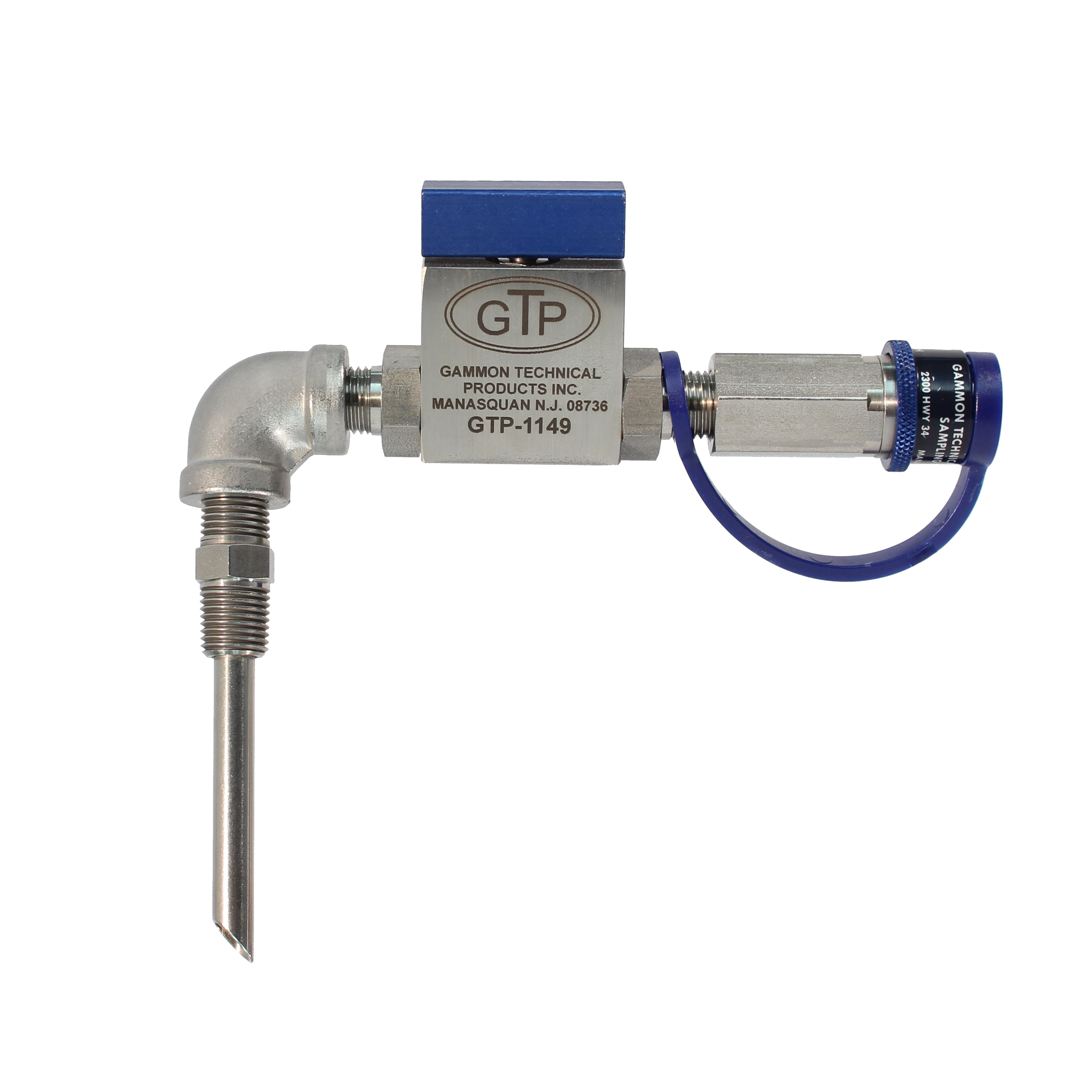
最近ある空港を訪れてそこの燃料ヤードへ行った時、上記と全く同様の状況を目撃しました。航空会社は私どものキットNo.1(図1参照)を指定していました。部品の組み込み方は完璧なのですが、位置が問題でした。8” サイズ T パイプの使われていないブランチの方に取り付けられていたため、少なくとも流れから6”(約1.5m)は離れていました。このお陰で、フィルター・セパレーター・エレメントの、たった1回の交換のために少なくとも600 ドル以上係りました。その理由というのが、フィルター・メンブレン(テスト)で捕えられたゴミの粒子を見て、どこかに欠陥があるものと作業者が信じたためなのです。テストに先立ってのフラッシングを完全に行わなかったために違いない、などとは言わないで下さい。このような状況では、ブランチ・コネクション内の燃料がメインの流れのものと同じになるまでには、大方の場合何百ガロンも使ってフラッシングしなければならないでしょう。

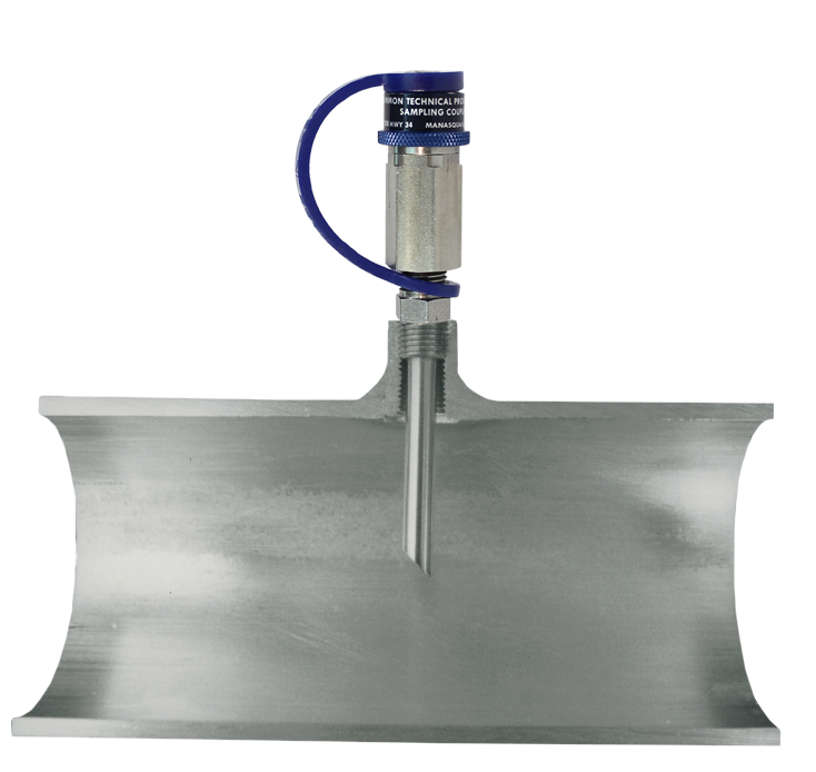
私どものサンプリング・プローブの真の目的は、メンブレン・テストがパイプを移送される燃料そのものに対して実施されるのを確実にすることにあります。そのプローブ(図2参照)は、パイプにカプリングを溶接するのと同じような感じで、どんなリデュースのブッシュにもはまるようになっています。

図1のもによる方法では、フィルター・メンブレンに到達する燃料はシステム流から離れると同時に、カーボン・スティールとは絶対接触しません。メンブレンまでの通路は全てステンレス・スティールの滑らかなもので、その口径は充分な流速が得られるように小さく、フラッシング中どんな残留物も生じないようになっています。

第4号「ジェット燃料用パイプ解剖」における流速についての話を覚えておいででしょうか。サンプリング・コネクションをフラッシングでき得る、ということはもっと重要ではないでしょうか。この故に、私どもはフィルター・メンブレン・テストの実施に先立ってフラッシング・ホースが使われるよう、この15 年に渡って懸命になっていたわけです。これまで出荷したミニ・モニター・キットはどれもフラッシングの流速が 10ft 毎秒(約3m 毎秒)になるようなものが付いています。ミニモニターのフラッシング・ヴァルヴ(あるいはミリポア社製のものも)は小粒ながら 50psi(約3.5kg/cm 2)に耐えるものです。ブリティン 68-3 のモデル GTP-1110 をご覧下さい。

お手持ちのサンプリング・コネクションを調べ、以下の事柄についてご検討下さい。

  1. 器具は、メインの流れからサンプリングするようパイプに位置しているかどうか。
  2. パイプに付けた器具は、きれいにフラッシングできる小形のものでしょうか。もし、そうでなかったら、検査器具を変えることで問題は解決します。
  3. 燃料がステンレス・スティール製のきれいなクイック・ディスコネクトに到達するまでの道程でカーボン・スティールのリデューシング・ブッシュやエルボー、又はカプリングを付けてはいませんか。もしそうなら錆びやすい旧式のクイック・ディスコネクトを依然として使おうというのでしょ
    うか。
  4. これまで、フィルター・セパレーターの上流側でメンブレン・テストをしたことがおありでしょうか。汚物がエレメントで除去されるかどうかを確認する、という点でこれは理に適った方法であると言えないでしょうか。

上述の項目中、4番目の問題は、実は私どもが常に関心を抱いている事の1つであります。フィルター・セパレーターの下流側でゴミも水も見い出されない、という事に安心していられるでしょうか。もしかしたら、初めからドライできれいな燃料であったかもしれません。すなわち、フィルターが事実完璧であった、という確証をどうやって掴むのでしょうか。私なら、フィルターで汚れが取り除かれたことがはっきりしたらもっと嬉しいですし、そしてフィルターをはたはたとたたきながら、こう言ってやりたくなります。「君、やってるな!」と。

(ザ・ギャムグラム第6号−以上−)

図1

図2

GamGram 6: サンプリング・コネクションの解剖2026-08-10T11:23:28-04:00

GamGram 4: ジェット燃料用パイプの解剖

“エンジニアード・プロブレム(Engineered Problem)”とはどのようなものかお判りでしょうか。 1つの定義としては、“やっつけ仕事” の技術とでも言えましょうか。ジェット燃料を扱おうとす る時、それは何か他の燃料と同じようなもの、すなわちガソリンより重いとか、燃料油より軽い とか、そんなふうな考え方をし始めると、この種の「技術」が顔を出して来るのです。2、3の 計算を手早く済ませ、キャメロン(米国ニューヨークにある出版社のポンプ部門 – マクドナルド商 会注)の水力データ・ブックにある圧力低下資料あたりをちょこっと眺めて、かろうじて働くだ けのポンプを選定した挙句、それを補うため2種類にわたるサイズのパイプをくっつけてポンプ が稼働するものと、決めてかゝる人があるとします。それで、大きい径のパイプは “将来のプラン ト拡張に備えるためのもの” などと正当化するわけです。まあ、何てことでしょう。

こゝに1つの事実があります。ある石油会社の基地からある空港まで輸送トレーラーで燃料が運ばれて います。その基地のローディング・ラックは1度に2車をまかなうことができるように、島の両側にそれ ぞれ1つづつのローディング・アームが設けられ、ラックへは 12″径のパイプが来ています。1,200gpm のフィルター・セパレーターが1基ラックから 100ft(約 30m)の場所にあります。配管の凡そ 70ft は8″で、これは地下にあり、最後の方 30ft が地上に出て 12″となり島の長さだけ伸びているわけです。 燃料は普通の輸送パイプラインで基地の貯蔵タンクに受入をしてフィルター・セパレーターへ行く前に予 めクレイを通して濾過しています。ある期間中フィルター・メンブレンがフィルター・セパレーターから 出たところで No. 2でありました。(ASTM D-3830 による。)

お客はフィルター・セパレーターを通した燃料を受け取るのですが、“白バケツ” テストを各トレーラー ごとに荷降ろしに先立って必ず行っています。

ところが、最近になってバケツの中の粒子の数があまり増えてきたため、お客側は積んで来た燃料の受 入を拒否し始めました。メンブレン・テストは色の点から見た場合、全く完全な状態なのです。そこで、 システム全体をチェックしましたところ、粒子がローディング・ラックに存在することが発見されました。 フィルター・セパレーターから出たところにはなかったのです。その粒子は殆どが酸化鉄で、コーヒーか すほどの大きさのものでした。

ラックの下の 12″のパイプが開かれました。パイプ壁の上部4分の3ほどがコーヒーかす大の錆で覆 われていました。パイプの底部3分の1は湿ったドロドロしたものや、錆、それにゴミが溜っていました。 掻き出すのにシャベルを使ったほどです。

計算により、1,200gpm 流量において径 12″のパイプ内の流速は毎秒 3.4ft(約 1.02m)にすぎなかっ たことが判っています。しかし、調査の結果、静電気発生の緩和を図るために、最大流量を 550gpm に 落とすよう技術部門から指示されていたことが判明しました。この信じられないほどの低い流れでは、毎 分 1.6ft(約 0.48m)のちょろちょろとした流速になってしまったのです。これがゴミの原因だったので す。すなわち、流速があまりにも小さかったため、パイプ内が洗い流されてきれいになれなかったのです。 タンク温度が地表温度より高くなるたびに、地下部分にある燃料から水が凝出し、又夜になって温度が下 がると、今度は地上 b 部の燃料から凝出するという事態が繰り返されたのです。

水はパイプから出られません。ドレンすることもできません。その結果、錆や泥状の物質が堆積する原 因となったのです。

この経験から学び取るべき第一の教訓は、燃料自体に管理を行わせる、ということです。管内を掃除し、乾いた状態にしておくことのできる流速を設計し、そしてそれを維持しなければなりません。少なくとも、毎秒6ft(約 1.8m)は必要です。

実地の経験から得た法則で知っておくと便利なのは、ジェット燃料に含まれる水は華氏温度の数値と大体同じ ppm の数値であるということです。例えば、80°F では 80ppm の水が燃料中に溶解し得る、ということです。地下パイプ内の温度 60°F に下がったとしますと、20ppm の遊離水分が析出すると考え られます。

水は凝結するためにタンク内で集まる、つまり溶解している状態から滴出していく、ということは何人 でも知っています。それなのに、配管内でも同じことが起きる、ということを、どうも多くの人が忘れて いるような感じですね。配管内の燃料の温度はタンク内のものに比べて嵩も少なく、さらされている表面 積も大きいため、もっと変化します(そして、より早く)。

最近完成した空港の給油システムでは、ハイドラント・システムが建設されるまでの向こう3年間、1 マイルほども長い 24″径の地下パイプで最高 2,400gpm の流量を扱うことになっている、ということ を知りました。その意味するところは、毎分 1.7ft(約 0.51m)の流速ということです。これはもうパイ プなどではない、全長1マイルのコンデンサーです。サンプからの水抜きもないのです。フィルター・セ パレーターのメーターに仕事を与え続けるような設計です。これなどキングサイズの “エンジニアード・プロブレム” でありましょう。

流速(Velocity =ヴェロシティ)計算早出し法

20 秒ほどで流速を計算できれば、ちょっとした数学の専門家のような感じですが、ここに秘訣があります。(流量とは異なりますのでご注意下さい)

手順 1. パイプ・サイズを2乗する。

手順 2. 得た数で、与えられた GPM (US ガロン毎分)を除する

手順 3. 0.4 を乗ずる。

(注)もし、GPM の代りに、時間当りバー レルの場合は、手順 2 でバーレルを 使い、 手順 3 では 0.3 で除します。

[例]パイプ・サイズ: 6″
流     量: 360GPM

手順 1. 6 × 6 = 36

手順 2. 360 ÷ 36 = 10

手順 3. 10 × 0.4 = 4

流速= 4ft 毎秒(約 1.2m 毎秒)

完全な公式としては、上記の等式で パイプ内径の実際値を使います。

V = 0.408 × GPM/d²  又は
0.286 × B/d²

(ザ・ギャムグラム第4号−以上−)

GamGram 4: ジェット燃料用パイプの解剖2026-08-06T11:35:41-04:00

GamGram 3: サ ン プ − その2

2月号では、大きなゴミがコアレサーを通らないで、フィルター・セパレーター・サンプに入 り込むのはどういう場合にか、ということについて説明しました。今回はコアレサーを通過する 非常に小さな粒子についてお話し致します。

フィルター・セパレーターを開けサンプ内を覆う細かい汚れの膜に気付いたことが、これまで何回お有 りでしょうか。横型容器では、この膜が壁面の半分ほどまで拡がっているでしょう。殆どの場合、それは 布切れで簡単に拭き取れます。粒子の一つひとつは細かくて見分けることができません。超微粒子なので す。

その事実から、フィルター・メンブレンの点では非常に良好な状態であることが判別できるわけで、決 して異常ではありません。もっとも、時折少量の水が存在しますが、出口側の燃料は乾いた状態です。し かし、フィルター・タンクの壁には数千もの悪条件のメンブレンを作り出すに充分な汚れが付着していま す。その汚れはコアレサーの下流側にあり、そのコアレサーはフィルターというわけです。何故こんな事 が起こるのでしょうか。

答は、汚れた水にあります。汚れはコアレサーを通して水の中に入って来ます。水滴となって容器の表 面やサンプの壁にくっつきます。それで、この非常に微細なゴミの粒子は、一つひとつの水滴の中に留まっ て、ついにはフィルター・タンクのエポキシ塗装に接触し付着してしまいます。水はドレンされるか再び 燃料中に溶け込むかしたわけです。ゴミを通してしまったのだから、そのコアレサーは不良である、と言 えるでしょうか。言えません。それどころかコアレサーは本来の機能を充分に果たしたのです。燃料がき れいであるかどうか、一体どう判断するのでしょうか。

コアレサー・エレメントが、何と素晴しい装置であるかを理解するには機会を見つけて、フィルター・セパレーターの試験室に行ってみるとよいでしょう。そこでは、レッド・アイアン・オキサイド(Red Iron Oxide =赤色酸化鉄)という名で知られる検査粉を使っています。その粒子は表に示す通り科
学的に等級付けられているもので、成分の 45%は 1/4 マイクロメーターあるいは 0.0001 インチ (0.00254mm)以下となっていることにご注目下さい。(それは、1インチの10 万分の1あるいは1千万分の1という ような大きさなのです。)

マイクロメーター
サイズ

レッド・アイアン・オキサイド
重 量 比
0 ~ 0.25 47.8
0.25 ~ 0.5 29.9
0.5 ~ 1.0 16.4
1.0 ~ 2.0 3.0
2.0 ~ 10.0 2.9
0 ~ 10.0 100.0
0 ~ 5.0 98.8

コアレサーには実際上、これらの微細な粒子を燃料から濾し分ける働きはありません。粒子の小さな塊 が集っていってコアレサーの中に溜ります。テストが進むにつれて、ゴミが通路を塞ぎ始めますので、圧 力の低下が大きくなっていきます。突然、研究員達は水を加え始めます。コアレサーはそのまゝ働き続け ますが、サンプ・ウォーターは鮮明な赤に染まります。燃料はきれいで乾いた状態のまゝです。

一体どんな事が起ったのかといゝますと、水が注がれて、コアレサー内のゴミに触れますと、ゴミは湿っ て塊が壊され元の粒子になります。燃料や繊維組織内に留 まらず、ゴミは水に入り込みます。その理由は 燃料よりも水分による「湿化」の方をゴミが好むからです。その結果、ミクロに近い細かなゴミがコアレ サーを通して水の中に入るわけです。燃料は、というと、それは清浄な状態を保ちます。

もし、フィルター・ヴェッセル・サンプ内に汚物の膜を見い出した時は、どうすればよいのでしょうか。 何よりも先ず、それはメンブレン・テストの結果が良好であった事を示すもので、決して危険な事態では ないのですから、警戒の要はありません。しかしながら、何故水が出て来たのか、その原因を発見するた めにシステム全体をチェックしなければなりません。エレメントの交換時には、常にフィルター・セパレー ターを充分掃除しなければなりません。汚物の膜を取り除きます。時として、その膜が水でも燃料でも剥 がれない場合がありますが、これは微生物による状態を示すものと信じられます。何故でしょうか。ある 期間その状態のまゝの水滴内では微生物が繁殖し始めることでしょうし、このような状況で発生した堆積 層は普通のゴミとは違って非常に取り除き難くなります。

トリソデューム燐酸塩(Trisodium Phospate)のような工業用洗剤は非常に効果的ですが、洗剤を使っ た後は、フィルター内に何の残留物もないよう表面を充分に水洗いしなければいけません。スティーム・ クリーナーは絶対に使わないで下さい。殆どが石鹸、すなわちフィルター・セパレーターに使用してはな らない強力なサーファクタント(脚注参照)を含んでいるからです。

(ザ・ギャムグラム第3号−以上−)

GamGram 3: サ ン プ − その22026-07-30T11:40:57-04:00

GamGram 2: サ ン プ − その1

私は子供の頃、ロス・アンジェラスに住んでいましたが、その折のこと、ゴミ回収トラックが 週に2度、私の家のそばまでやって来ていました。その臭気は表現のしようもないほどでしたが、私は作業員がいつもゴミを空けながらゴミ缶から出てくるものに目を注いでいることに気付きま した。ある日、何を探しているのかその人に尋ねてみました。「坊や、」その人が言いました。「面白いね。ゴミ缶から出てくるもので、まあそれぞれ人のいろんな事が分 かるんだよ。」今私は、フィルター・マンとして、彼のこの哲学が正しいことを証明できます。

我々はフィルターとか油だめで回収したゴミから、あなた方の油とその油の扱い方について、あなた方 ご自身よりも多くの事柄を知ることができるかも知れません。

フィルターのサンプを検査して知り得るものは非常に大きな問題であり、ギャムグラムでもこの点を多 く扱いたいと思います。本号では、フィルター・セパレーター・サンプ内の大ぶりのゴミに関してのみ話 を進めましょう。

ゴミはフィルター・セパレーター・サンプにどのように入込むのでしょうか。

ご承知のように、全て現今のコアレサー(第一段階目のエレメント)は液がインサイドからアウトサイ ドへ流れるように設計されています。サンプはコアレサーの外側に溜って来る水を集めるためのものです。そしてコアレサーも又フィルターであります − と、こゝで疑問が生じるでしょう。どういうふうにし
てゴミがサンプに溜るのか、という。コアレサーの機能が完全ではないのでしょうか。違います(もっと も、ほんの稀にはそういう事もあるでしょうが)。

ある寒い冬の夜中のこと、私はあるお客からの電話で、暖かいベッドから起き出すはめになったことが ありました。その人はこう私に言いました。「君のところから先月買ったこのいまいましいエレメントだ がね、大きなパン切れとゴミを通しちまった。サンプ・ドレンから出て来てるよ。」圧力は絶対大きく下がっ てなかった、とも言い張りました。私は吹雪の中を300 マイル(約483 キロ)も車を駆り、翌日に はいずれも目に非難の色を浮かべている職員の一団に面会していました。白い幾つかのバケツの底に横たわる証拠なるものも見せられました。それは恐るべきものでした。殆どがピンの頭ほどの大きさで、そう・・、コーヒーかすのようなものでしたし、あるものは、かなりの大きさでした。

新しいエレメントを取付けることに彼等の間で話がまとまりましたが、それは私の競争相手のものでし た。フィルター・メンブレンによる色相試験では問題がなかったにも拘わらずです。その日の夕方には新 しいエレメントがタルサから航空便で届きました。私達は現場作業員達の手で私のエレメントが取り外さ れるのを、フィルターの周りに集って灯りを頼りに見守っていました。取り外されるエレメントを私は検 査のため工場へ送ることにしていました。

必要な範囲で燃料を抜いてから、カヴァーが開けられました。皆でヴァルヴやパイプをよじ登って梯子 の上から覗き込みました。と、どうでしょう。燃料は水晶のように透明でエレメントは実に完全そのもの のように見えました。一方、サンプは汚れきっていたのです。

恐ろしいことに、彼等は燃料を全部抜き取らないでエレメントを外しに掛かったのです。「それだ、判っ た!」「そんなことはしないで下さいよ。」私はもう本当に嘆願しましたね。そう言っているうちにも最初 のエレメントはもう外されてしまいました。その時、私は勝ち誇る気持で懐中電灯がキラキラと映しだす 燃料を見るように彼等に向かって言いました。まあ!ヴェッセル全体が光の中ではっきりと浮かんで見え る様々なタイプの汚れた粒子でメチャメチャになったのです。

コアレサーの中に捕えられていた汚れの粒子が、エレメントを外した時にエレメントのセンター・チュー ブから残っていた燃料を通ってヴェッセル内に流れ出て来たのでした。

このエピソードはもう何年も前にあった事で、私もしばしば語ってきましたため、世界中に知られてい るのではないか、と思うほどです。しかし、そうはいかないようで、先ずタンクの燃料を空にしないでエ レメントを外そうとする人が居ることを1ケ月の内に1件は見つけられるのではないでしょうか。

フィルター・セパレーターのドレンをサンプ・ヴァルヴを通して行う場合、コアレサー内の油はコアレ サーを経由して出てきます。油がエレメントから急激にほとばしり落ちるということはありません。この 2つの条件によってゴミがエレメント内に保持されるのです。もっとも、何人もそれを見ることはできま せんが。それで道理に適う、というものではないでしょうか。

《断片考》殆どの横型フィルター・セパレーターでは、この種の問題がありません。(ふたを 開けるためには)先ず、ドレンを行わなければならないからです。

もし、サンプ内に大きなゴミの粒子が見つけられたとしたら、それは、コアレサーが破けたか、取付け 自体が悪かったか、又あるいは前回エレメントを交換した際にサンプを良く掃除しなかったか、大抵この 内のどれかが原因であることに間違いはないでしょう。

現在のコアレサーは、油中で分離していることが人間の目で確認できるほどに大きなゴミを通すことは ありません。

このため、フィルター・メンブレン・テストを行うわけです。メンブレンは 0.8 マイクロメーター(ミ クロン)の値であり、目で見えないゴミも容易に捕捉します。メンブレンがこのような細かい粒子で覆わ れてしまった時には、当然メンブレンの汚れに気が付くでしょう。黒ずんで来るほどに、汚れがひどくなっ ているのです。

ASTM D-3830 は、色相方式によるメンブレンの評価方法を説明しています。私どもは大いにこの方 法を支持しています。

ところで、1ミクロンの大きさはどれ位でしょうか。この用紙の厚さがほゞ 75 ミクロンです。

(ザ・ギャムグラム第2号−以上−)

GamGram 2: サ ン プ − その12026-07-30T11:40:21-04:00

GamGram 46: Recepción del Combustible

A menudo se dice que la operación de reabastecimiento es la “última línea de defensa”, donde se asegura que el combustible entregado a la aeronave es el adecuado, libre de contaminantes Si esto es cierto, y seguramente lo es, entonces la operación de recibir el combustible es un aspecto crítico en la cadena de suministro porque desafortunadamente, no siempre se trata de esa manera.

Hace poco el conductor de un camión cisterna de transporte arribó al punto de descarga de un aeropuerto diciendo que tenía una carga de Avgas. El operador de turno le pareció raro porque no le habían sido notificado esa entrega de combustible; pero se encogió de hombros y le oriento al conductor que pasara al almacén de combustible (Error #1). Luego conectó las mangueras de recepción a la cisterna sin antes realizar el ensayo visual con la cubeta blanca. El cubo se estaba ubicado a menos de 10 pies de distancia (Error #2) y finalmente se dirigió al chofer examinando la documentación que él traía. Pasó por alto que el nombre de la compañía ni siquiera estaba plasmado en los papeles y paso por alto que la entrega era otro suministrador de combustible del mismo aeropuerto (FBO), y además, no vio que la boleta tenía escrito el término turbocombustible (Error #3). Llamó a su jefe por la radio, quien le preguntó si había hecho una prueba visual de control con el balde blanco y esté pensando que era una pequeña mentira piadosa afirmó que lo había realizado (Error #4). Su jefe le dijo que siguiera descargando lo que quedaba en el compartimento del camión (el camión tenía varios compartimentos) y que luego enviara el camión al almacén del competidor para descargar el resto del combustible. Esto fue lo que hizo.

Por suerte el jefe tenía orgullo y era muy profesional, rasgos muy escasos en estos días. Se levantó de su escritorio y se dirigió hasta las instalaciones de su competidor para verificar con un doble chequeo. Después de revisar la documentación de la paila, olio el tanque vacío del camión desde la escotilla (tapa) y cerró apresuradamente el aeropuerto para los aviones que consumían Avgas y ordenó a una aeronave la cual estaba en el aire que hiciera un aterrizaje de emergencia. Se encontró que en los tanques auxiliares de la aeronave estaba el combustible mezclado: mitad Avgas y mitad turbocombustible (Jet Fuel).

Hay muchas historias como esta, con contaminantes desde diésel y líquido anticongelante, hasta abono y leche (¡sí, leche!). La lección es obvia, pero todos los años ocurren ejemplos similares como este. Por eso escribimos este GamGram.

PROCEDIMIENTO MÍNIMOS RECOMENDADOS PARA LA RECEPCIÓN DEL COMBUSTIBLE

Ante todo ¡Asegúrese de que su compañía petrolera y/o cliente (la aerolínea) aprueben cada procedimiento operacional antes de adoptarlo! Una guía excelente es el Estándar para el Control de Calidad del Combustible de Aviación en los Aeropuertos para la aerolínea conocida como ATA 103. Esta se puede obtener llamando al teléfono 202-626-400 o puede obtenerla online https://publications.airlines.org.

  1. Inspeccione y chequee toda la documentación que trae la cisterna. Asegúrese de que todos los datos sean correctos, especialmente el tipo de combustible y el número del equipo de transporte del camión.
  2. Inspeccione las conexiones de descarga, limpie cualquier residuo o contaminación. y conecte el cable de tierra al punto requerido.
  3. Si va a utilizar la manguera que trae consigo el camión, asegúrese que esté limpia y que las juntas estén en su lugar y en buenas condiciones.
  4. Si va a utilizar la propia bomba del camión para transferir el combustible, asegúrese de que esté correctamente drenado los conductos y la propia bomba de cualquier producto anterior.
    NOTA: Aunque los conductores del camión a menudo le dirán que no tiene que revisar el combustible, ¡hágalo de todos modos! Los errores ocurren muy a menudo y por ello no puede confiar en el control de calidad que realiza otra persona.
  5. Antes de cualquier control de calidad es mejor esperar 10 minutos para que el combustible contenido en el tanque se asiente, realizar el ensayo de control visual conocido como ‘claro y brillante’ utilizando la cubeta blanca, también puede usar un frasco de vidrio trasparente por ejemplo: un tarro de mayonesa para observar el combustible través del mismo (no olvide agitarlo antes en forma de torbellino). Si la primera muestra no es buena, haga otra y tal vez otra más. (Para mayor información consulte la publicación de ASTM número MNL-5 para conocer el procedimiento o el ATA-103).
  6. Si el combustible pasa la prueba visual con el balde blanco, proceda a continuación con el ensayo de densidad utilizando un hidrómetro, si es posible. (Consulte ASTM MNL5 para ver un procedimiento, o nuestro GamGram 19). Desafortunadamente, muchos aeropuertos no realizan estas pruebas.
  7. Si el combustible pasa la prueba del hidrómetro, proceda a realizar el ensayo para detectar el contenido de agua utilizando los detectores Shell o Exxon/Velcon. Las pruebas de Hydrokit son muy buenas o también se usa el Metrocator, pero es algo menos común. (El Aqua-Glo producido por nuestra compañía es mucho más preciso para detectar el contenido de agua por lo que se utiliza mayormente para los análisis de laboratorios).
  8. Solo después de completar todas las pruebas, es que debe conectarse y prepararse para el descargue del combustible
    NOTA: Se puede usar un muestrador de circuito cerrado para realizar de manera más conveniente las pruebas 5-9. Vea nuestro Boletín 138.
  9. ¡Aún no has terminado! Asegúrese de que su tanque tenga suficiente capacidad para recibir el volumen de combustible que planea descargar y luego realice una verificación previa de su sistema de protección contra sobrellenado de los tanques.
  10. Realice la descarga del combustible.

Antes de usar el combustible descargado, le recomendamos que configure su sistema para recircular el mismo y ejecute una prueba de membrana filtrante para asegurarse que no contenga partículas en exceso (ver ASTM MNL-5, D-2276/IP-216). Si ha tenido problemas de contaminación por partículas, es posible que desee realizar esta prueba durante la descarga. Para acelerar la ejecución de este ensayo prueba, cierre parcialmente la válvula aguas abajo hasta alcanzar 20-30 psi p incrementando con esto el flujo a través de la capsula con la membrana.

Recuerde: si usted o su gente alguna vez dicen: “Esto no puede suceder aquí”, ¡sucederá! Los entrenamientos, la formación del personal, el equipamiento adecuado y las listas de verificación son inútiles si no hay profesionalismo y orgullo propio.

Si nunca ha recibido una carga de combustible fuera de especificaciones o incorrecta, y por tampoco ha recibido el crédito por salvar vidas, al menos usted puede mantener la cabeza en alto y tener orgullo de saber que habría detectado un problema, en caso que se hubiera presentado.

La mayoría de las veces el prestigio es la única recompensa a la profesionalidad, pero es suficiente, ¿cierto?

GamGram 46: Recepción del Combustible2026-08-27T09:47:00-04:00

GamGram 46: Receiving Fuel

It is often said that the refueling operation is the “last line of defense”, insuring that the fuel going to aircraft is the correct fuel, contaminant free. If this is true, and surely it is, then receiving fuel is a very critical element in the supply system. Unfortunately, it is not always treated that way.

In one recent case, the driver of a delivery transport truck (Bridger) arrived at an airport saying he had a load of Avgas. The man on duty thought it was odd because he had not been told of a fuel delivery He shrugged his shoulders and told the truck driver to pull into the fuel farm (Mistake #1). He then connected up the delivery hose without a white bucket test; a bucket was less than 10 feet away (Mistake #2). He then finally looked at the driver’s paperwork. He did notice that his company’s name was not on the papers, the delivery was meant for another FBO at the same airport. He did not notice the term “Jet Fuel” on the ticket (Mistake #3). He called his boss on the radio, who specifically asked if he had done a white bucket test. Feeling it was a small lie, he said “yes” (Mistake #4). His boss told him to continue unloading the rest of the truck’s compartment (the truck had several compartments) and then send the truck to the competitor’s fuel farm to unload the rest of the fuel. This was done.

Fortunately, his boss had pride and professionalism, traits in all too short supply these days. He got up from his desk and drove over to his competitor’s facility to double-check. After checking the paperwork and smelling the empty truck tank at the hatch (cover), he shut down the airport to Avgas aircraft and ordered one aircraft that was already in the air to make an emergency landing. It was found that the aircraft’s auxiliary tanks were half Avgas and half Jet Fuel.

We have heard of many, many stories like this one, with contaminants from diesel to deicing fluid to liquid fertilizer to milk (yes milk!). The lesson here is obvious, but we hear similar examples like this every year. This is why we have written this GamGram.

RECOMMENDED MINIMUM FUEL RECEIPT PROCEDURE

Make sure your oil company and/or airline customer approves of every procedure before you adopt it! An excellent guide line is ATA – 103, the airline standard. This can be obtained by calling 202-626-400.

  1. Inspect the paperwork. Make sure all data are correct, especially the fuel type and trailer/bridger number.
  2. Inspect the unloading connection and clean off any debris/contamination. Connect the ground wire.
  3. If you are going to use the truck’s hose, make sure it is clean and that the gaskets are in place and in good condition.
  4. If you are going to use the truck’s own pump to transfer the fuel, make sure it is properly drained of any previous product.
    NOTE: Although truckers often will tell you that you don’t have to check the fuel, do it anyhow! Errors occur and you cannot rely on someone else’s quality control.
  5. It is best to wait 10 minutes for the tank to settle. Make sure to do a white bucket test. Do Not flush before a test. The fuel should appear “Clear and Bright”. A mayonnaise jar can also be used for inspection of the fuel in the bucket. If the first sample is no good, do another and perhaps even another. See ASTM publication number MNL-5 for the procedure, or the ATA-103.
  6. If the fuel passes the white bucket test, proceed to a hydrometer test, if possible. (See ASTM MNL-5 for a procedure, or our GamGram 19). Unfortunately, many airports do not perform this test.
  7. If the fuel passes the hydrometer test, proceed to the water test. The Shell or Exxon/Velcon Hydrokit tests are both good, and the Metrocator is also used, but is somewhat less common. (Of course our Aqua-Glo is a more precise lab quality test for water content).
  8. Only after all of the tests are completed should you connect and prepare to unload.
    NOTE: A closed circuit sampler can be used to more conveniently perform tests 5-9. See our Bulletin 138.
  9. You are not done yet! Make sure your tank has enough capacity for the new delivery and then perform a pre-check of your over-fill protection system, if so equipped.
  10. Unload.

Before you use the fuel we recommend you set up to recirculate and run a filter membrane test to insure that you have no excessive particulate (see ASTM MNL-5, D-2276/IP-216). If you have had problems, you may wish to perform this test during unloading. To speed up the test, partially close a downstream valve to build up 20-30 psi so as to speed up the flow through the filter membrane.

Remember – If you or your people ever say, “It can’t happen here”, it will! Training, equipment and checklists are useless without pride and professionalism. Double-check everything, assume nothing and trust no one, but when you find the job well done, say so.

If you never receive a bad or incorrect load of fuel, and never receive credit for saving lives, at least you can hold your head high and have pride because you know you would have caught a problem, had it come your way.

Most of the time pride is the only reward for professionalism, but it is enough, don’t you agree?

GamGram 46: Receiving Fuel2026-05-28T10:56:57-04:00

GamGram 45: Problemas con el Brazo de Succión Flotante

Los accesorios utilizados en los tanques de almacenamiento para extraer el combustible de aviación conocidos como brazo de succión flotantes son a primera vista elementos simples. ¿Qué puede salir mal con una succión flotante? Aunque, podría tener fugas en las uniones bridadas o la articulación giratoria atacarse ¿qué más? Hace años, cuando empezamos a fabricarlos, pensamos que eso era todo lo que podía pasar también. Pero con los años hemos aprendido que hay además otras cosas que pudieran estar mal. En una ocasión, al suministrar un gran bazo de succión flotante con un diámetro de 16″ al comenzar a usarlo sobresalía tanto del combustible que la boca de aspiración estaba en el aire y el brazo vacío. El operador no pudo extraer combustible del tanque. Resulto ser algo desconcertante, por decir lo menos. Muchos estarán con cara de risa al creer saber por qué sucedió esto, pero la mayoría de ustedes están equivocados pues no había pasado lo que generalmente ocurre: La articulación del codo giratorio no se había trabado, ni tampoco el cable de comprobación estaba enredado, ni el brazo atascado con la columna soporte del tanque.

No los mantendré en suspenso por más tiempo. La causa resultó ser que el operador había rellenado accidentalmente el brazo inyectándole aire. ¿Cómo pudo hacer esto? pues cuando vaciaron por completo otro tanque del sistema conectado al mismo colector, este quedó sin combustible y con aire atrapado. Al abrir la válvula del tanque el combustible contenido en el brazo empezó a fluir hacia es colector y el aire hacia el tubo del brazo; el aire de la línea se desplazó hacia el brazo con gran rapidez disminuyendo su densidad media, aumentando su flotabilidad. Como resultado hizo que este se elevara por encima del nivel del combustible evitando que el combustible penetrara en el mismo y lo llenara convirtiendo al propio brazo en un flotante, ¿entonces? algunos de ustedes conocían la causa, pero no ¡muchos!

El problema anterior solo ocurre en un tanque con la conexión de succión colocada en la parte baja de su costado, no obstante varias complicaciones surgen con cualquier succión flotante, por eso decidimos escribir este GamGram con elementos a tener en cuanta al especificar o instalar uno:

  1. Como se describió en el caso anterior, lo brazos de succión flotantes colocados en tanques verticales (o tanques horizontales con conexiones a colectores) deben contar con algunas de las siguientes aplicaciones:
      • Colocar una tubería de diámetro pequeño con una válvula manual que interconecta la pared del tanque con la tubuladura de conexión brazo flotante. Si necesita abrir esta válvula porque el brazo se convirtió en un flotante, la columna líquida del tanque hace que el combustible fluya a través de esa tubería y penetre en el brazo una vez desplazado el aire y de esta forma el brazo recupera su densidad sumergiéndose en el combustible nuevamente.
      • Taladrar un pequeño orificio en el costado del brazo, aproximadamente a un tercio del camino desde el pivote hasta el flotador. Esto permite que el combustible penetre en el brazo a través del orificio y desplace el aire en su interior. Surge un problemita pero sin efecto negativo grande como para ser tomado en cuenta: Una pequeña cantidad de combustible no tan limpio como el de la superficie será succionada por el orificio
      • Agregar una válvula especial al codo giratorio. Se supone que esta válvula se abre para llenar el brazo de combustible en caso de que este haya cogido aire. Suena como una buena idea, pero las válvulas de este tipo deben fabricarse con mucha precisión, o no funcionan o se abren en condiciones normales de flujo y no será mejor que el orificio de purga descrito anteriormente.
  2. Otro problema experimentado en las succiones flotantes es algo similar al punto 1 anterior, ocurre en cualquier estilo de tanque. También resulta en tener el brazo convertido en “flotador” pero la causa es diferente. Al llenar un tanque vacío, el nivel de combustible sube hasta llegar a la entrada de succión flotante; pero como la entrada está colocada mirando hacia abajo y el aire dentro del brazo queda atrapado, a medida que aumenta el nivel de combustible, el brazo flotando es empujado afuera del combustible. Esta es la razón por la que muchos fabricantes de succión flotante (incluido Gammon Technical Products) perforan a la entrada del brazo pequeños orificios en la parte superior del codo. A medida que se llena el depósito, el combustible penetra en el interior del brazo porque desplaza el aire el cual sale por estos pequeños orificios de la parte superior. Usamos un orificio de 1/8″ para brazos de hasta 4″, y orificios de “sangrado” más grandes para brazos de mayor tamaño. Asegúrese de que su nueva succión flotante tenga un orificio para purgar el aire antes de cerrar el tanque.
  3. Muchos problemas de aire o fugas en la succión se dan en los tanques horizontales, con las conexiones desde la parte superior, a estas dificultades se les denomina “Problemas de cebado de la bomba”, pero a menudo son causados por la succión flotante instalado y es el resultado de una de estas tres causas:
    • Las bridas no ajustadas con los pernos en paralelo.
    • Las juntas o empaquetaduras utilizadas no son compatible con el combustible.
    • La conexión de la tubería en el techo del tanque tiene fugas.

    Una de las razones de tales escapes es que el contratista prueba la tubería sin instalar el brazo de succión flotante ya que solo se fijan si la tubería tiene salideros fuera de las paredes del tanque.
    El principal problema es que el instalador suele pararse en una escalera dentro del tanque, con poca luz y en esa posición es muy difícil apretar correctamente la tubería en el techo del tanque en esta posición, también es complicado atornillar las bridas correctamente para sellar la unión. Es importante que la junta de la brida sea compatible con el combustible. Increíblemente los instaladores a menudo no tienen tanto conocimiento sobre el material de las juntas.Estas cuestiones resultan obvias, pero se estima que al menos el 25 % de todos los tanques con brazo instalados con la succión desde la parte superior tienen problemas como resultado de fugas de succión que falsamente se conocen como de “cebado de la bomba”. (Consulte el GamGram 41 para obtener más información sobre el tema.)

  4. Otro problema con las succiones flotantes tiene que ver simplemente con el tamaño incorrecto (diámetro). Si el diámetro de la succión flotante es demasiado pequeño, tendrá problemas no logra el caudal requerido porque la bomba tiene que succionar demasiado fuerte y el combustible se convierte en burbujas (vapor). (OK, para los ingenieros, saben que es un poco más complicado, pero no tenemos suficiente espacio en este boletín para una explicación técnica completa)
    Primero analice en que condición opera su sistema bajo la taza de flujo más alta. Esto generalmente suele ser durante la operación de recirculación. Para nosotros no es aconsejable obtener velocidades flujo por debajo de los 4 ft/seg.(1.2 m/s), ni por encima de los 7 ft/s (2,1 m/s). Hemos logrado con éxito velocidades de línea de succión hasta 9 ft/s (2.74 m/s), pero solo en combustibles tipo jet (turbocombustible) y solo en sistemas con tanques verticales aéreos ubicados muy cerca de la bomba.
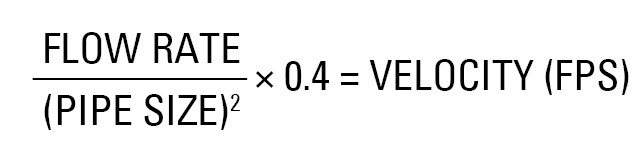
    Realice el cálculo de la velocidad mediante la siguiente formula:

    Esta es la “Fórmula de Gammon” la cual elaboramos después de visitas reiteradas al libro que contiene las tablas relacionadas con esto. Esta regla es muy precisa y conveniente. Por ejemplo: Al calcular el tamaño correcto de la tubería para un brazo de succión flotante con una taza de flujo requerida de 200 GPM. Tomaremos un tubo de diámetro 3” (75 mm) daría como resultado una velocidad excesiva de 8,9 ft/s (2,7 m/s). Una tubería de 4 “da 5 ft/s ¡Mucho mejor! (OK ingenieros, sé que ustedes saben cómo calcular la altura neta positiva de aspiración “NPSH” de la bomba positiva y compararla con la curva de la bomba, pero no todos ¡lo hacen!).
    Las tuberías de presión, (aguas abajo de la bomba), suelen tener menos diámetro que las de succión, porque la caída de presión en ellas no hace daño y la bomba puede lidiar con eso, Sin embargo en el lado de la succión, una caída de presión excesiva hace que el combustible comience a burbujear originando vapor y con ello se interrumpe la secuencia de bombeo (cavitación) y pierda el flujo de combustible. La tubería de presión o las mangueras de suministro a la aeronave, utilizadas para un caudal de 200 GPM suelen ser de 2 desarrollan una velocidad tan rápida como 20 ft/s(6 m/s).
  5. Otro problema que generalmente se atribuye a la bomba es el tener un punto alto en la tubería de succión. Usualmente la tubería de succión utilizada con una bomba centrífuga debe ser horizontal o ligeramente inclinada hacia la entrada de la bomba, sin “puntos altos” ya que pueden atrapar aire. Si hay un punto alto en la tubería de succión, las bombas centrífugas presentan problemas similares a los del punto 4 r. Sin embargo, las bombas de desplazamiento positivo son mucho más tolerantes con los puntos altos.
    Por ejemplo, si planea usar una bomba centrifuga para succionar desde un tanque aéreo, es mejor que no coloque la tubería subiendo para que la bomba succione desde la parte superior, de lo contrario tendrá un punto alto serio. Tenemos entendido que los 50 estados de EE. UU. Tienen como requerimiento “conexiones superiores”, por lo que parece que necesitarán una bomba de desplazamiento positivo.
  6. Si su tanque presenta una altura mayor que el diámetro y permite que un brazo de succión flotante se eleve hasta quedar vertical se mantendrá así y no bajará nuevamente. Esta es la razón por la que, diseñamos nuestro brazo de succión flotantes más pequeños para que no se eleven más de 45°, y nunca permitimos que ningún brazo de succión flotante se eleve más de 55°. ¿Cómo aseguramos esta condición? Se coloca un brazo lo suficientemente largo para que el flotador toque el techo del tanque antes de que alcance un ángulo mayor de 55°, o conectando un cable desde el fondo del tanque al brazo que restringe el ángulo que puede alcanzar el brazo. Lo llamamos “cable de sujeción”.
    En un tanque de 35′ de diámetro y 40′ de alto, el brazo puede estar restringido para elevarse solo 27′ del fondo cuando el tanque está lleno, mientras que el nivel de combustible será quizás de 38′. Esto puede preocupar a algunos de ustedes, pero la calidad del combustible a este nivel en el tanque no es mucho peor que el que está pegado a la superficie, y a su vez es mucho mejor que el del fondo del tanque. La única alternativa para tomar siempre el combustible cercano a la superficie es poner un brazo de succión flotante, articulado, es decir, con dos rótulas y brazos; resulta mucho más caro y requiere cables guías, lo podemos hacer pero no lo recomendamos en la mayoría de los casos.

A pesar de su simple apariencia el uso de este dispositivo es muy interesante y requiere de mucha atención. Para obtener más información sobre el diseño de los sistemas de combustible ver GamGram 38 y GamGram 39. Ver GamGram 41 para problemas de cebado de la bomba.

GamGram 45: Problemas con el Brazo de Succión Flotante2026-08-27T09:48:57-04:00

GamGram 45: Floating Suction Problems

Floating suction assemblies are simple items at first glance. What can go wrong with a floating suction? Well, the float could leak or the swivel could stick, but what else? Years ago when we first started manufacturing them, we thought that was about it too. But over the years we have learned that there are many other things that can go wrong.

In one case, a large 16” diameter floating suction assembly that we supplied was sticking up out to the fuel so far that the inlet was in the air and the arm was empty. The operator could not get any flow. It was perplexing, to say the least.

Many of you are smiling right now, because you think you know why this happened, and most of you are wrong. The swivel did not stick, the retrieving cable was not tangled, and the arm was not jammed against a support column.

I will keep you in suspense no longer. The cause turned out to be that the operator had accidentally backfilled the arm with air. How? When they emptied another tank they had also emptied the suction line common to both tanks. When they then opened the valve on the tank that held our floating suction, the air in the pipe rushed into the floating suction arm, and the fuel in the arm rushed into the pipe. Before fuel in the tank could flow into the arm, the arm had already gained enough buoyancy to cause it to pop up, raising the inlet above the surface of the fuel. This is called a “floater”. OK, so some of you knew the cause, but not many!

The above problem can only happen on a tank with the outlet connection placed low on the side of the tank, but there are a number of things that can go wrong with any floating suction and we have decided to write this GamGram to list things that should be kept in mind when specifying or installing one.

  1. As described above, floating suctions in vertical tanks (or horizontal tanks with end connections) should have one of the following:
      • A small pipe with a manual valve can be run from the side of the tank to the suction pipe outside of the tank. This valve can be opened to fill the floating suction should it become a “floater” as described above.
      • A small hole can be drilled into the side of the arm about a third of the way from the swivel to the float. This will allow the arm to refill should it become filled with air. This hole will allow the arm to draw a small amount of “less clean” fuel from a level in the tank well below the surface, but any negative effect will be small.
      • A special valve can be added to the swivel. This valve is supposed to open and fill the arm should the arm fill with air. This sounds like a good idea, but valves of this type must be made very exactly, or they will either not work or will open under normal flow conditions and will be no better than the bleed hole described above.
  2. Another problem experienced in floating suctions is similar, but can happen in any style tank. It also results in having a “floater”, but the cause is different. When filling an empty tank, the fuel level rises until it reaches the floating suction inlet. But because the inlet is turned downward, and the air inside the arm is trapped, as the fuel level rises, the arm floats up out of the fuel.
    This is the reason that many floating suction manufacturers (including GTP) drill small holes in the top of the inlet end of the floating suction elbow. As the tank fills, the fuel can enter the arm because the air can get out by way of these small holes. We us a 1/8” hole for arms up to 4”, and larger “bleed” holes for larger arms. Make sure your new floating suction has a bleeder hole before you close up the tank.
  3. In horizontal tanks with top connections we have experienced many, many air problems – suction leaks. As described in GamGram 41, these problems are usually called pump priming problems, but are often caused by the floating suction installer. The problem is one of three things:
    • The flanges are not parallel when the flange bolts are tightened.
    • The gasket used is not compatible.
    • The pipe connection in the roof of the tank leaks.

    One reason for such leaks is that the contractor tests the piping without the floating suction installed. They never consider that the pipe INSIDE the tank could leak because they are concerned only with leaks that release fuel onto the ground.
    The main problem is that the installer is usually standing on a ladder inside the tank, in poor lighting, and working overhead. It is very hard to get the pipe properly tightened into the tank roof in this position, and it is hard to bolt the flanges together in parallel. It is also critical that the flange gasket be compatible with the fuel. Believe it or not, the installers often are not that knowledgeable about gasket material.
    These things may sound obvious, but we estimate that at least 25% of all horizontal tank fuel systems have problems as a result of suction leaks. These problems are usually falsely called “pump priming problems”. See GamGram 41 for more on this.

  4. Another problem is simply in choosing the incorrect size. If the floating suction is too small, you will have problems achieving the required flow rate. The reason is that the pump has to pull too hard, and the fuel breaks into vapor (OK, engineers, so it is a little more complicated than that, but we haven’t the room here for a full technical explanation)
    First figure out the condition under which you will have the highest flow rate. This is usually during recirculation. We do not like to see velocities below 4 feet per second (FPS) or above 7 FPS. We have successfully achieved suction line velocities as high as 9 FPS, but only on jet fuels, and only on systems with above ground vertical tanks located close to the pump.
    You can perform the following calculation:

    This is “Gammon’s Formula” which we worked out after too many trips to the book of tables. It is very accurate and convenient. For example, let’s calculate the correct pipe size for a floating suction and suction pipe for 200 gpm. A 3” pipe size would result in an excessive velocity of 8.9 FPS (feet per second). A 4” pipe gives a much better 5 FPS. (OK engineers, I know you know how to calculate net positive suction head and compare it to the pump curve, but not everyone does!)
    Pressure pipes, downstream of the pump, are smaller than suction pipe, because a little pressure drop does no harm here. (On the suction side too much pressure drop results in the fuel breaking into vapor and you lose flow rate). Pressure pipe and refueling hose for 200 gpm is usually 2”, which is a fast 20 FPS.
  5. Another problem usually blamed on the pump is a suction high point. The suction pipe used with a centrifugal pump should either be horizontal, or sloped slightly up to the pump inlet, with no “high points” to trap air. If there is a high point in the suction pipe, centrifugal pumps will experience problems similar to those of item 4 above. Positive displacement pumps are much more tolerant of high points.
    For example, if you plan to use an aboveground tank with a centrifugal pump, you had better not have the suction pipe leaving the tank at the top or you will have a serious high point. It is our understanding that all 50 states in the USA require “top connections”, so it looks like you will need a positive displacement pump.
  6. If you allow a floating suction arm to rise far enough, it will go perfectly vertical. If it does so, it will stay that way. For that reason, we design our smaller floating suctions to rise no more than 45 degrees, and never allow any floating suction to rise more than 55 degrees. How? By either having an arm long enough so that the float touches the tank roof before it reaches a high angle, or by attaching a cable from the tank bottom to the arm that restricts the angle that the arm can reach. We call this a “restraining cable.”
    In a tank 35’ in diameter and 40’ high, the arm may be restricted to rise only 27’ off the bottom when the tank is full, while the fuel level will be perhaps 38’. This may worry some of you, but the quality of the fuel at this level in the tank is not much worse than at the surface, and is much better than at the tank bottom. The only alternative is to put in an “articulated” floating suction arm, which has two swivels and arms. This is much more expensive and requires guide cables. We do make such designs, but recommend against them in most cases.

It is interesting that so much is important in the use of such an apparently simple device. For more information on fuel system design see GamGram 38 and GamGram 39. See GamGram 41 for pump priming problems.

GamGram 45: Floating Suction Problems2026-05-28T10:56:49-04:00

GamGram 44: Control de Caída de Presión del Filtro Separador

Cuando era niño, escuché la historia de un evento que sucedió en un pueblo cercano. Un camión de gran tamaño y altura quedó atrapado debajo de un puente de muy poca elevación. En medio de la confusión nadie supo cómo sacar el camión. Entre los que estaban cerca del lugar, había un niño que insistía tenazmente en hablar con un oficial de la policía y este no le prestaba atención alguna. Finalmente el policía le permitió expresar lo que tanto quería explicar: Le sugirió sacarle un poco del aire a los del aire neumáticos del camión y, por supuesto al disminuir la altura, funcionó. Recuerdo esta anécdota porque a veces me siento un poco en la misma posición del chico.

El mensaje de este Gamgram es que existe una solución económica y elegante al problema de los elementos colapsados o reventados en el filtro separador. (Respecto al filtro absolvente de agua “monitor”, ver GamGram 56 y GamGram 65.)

La instalación de un interruptor que accione cuando la presión diferencial del filtro llega al límite estipulado es la primera solución al problema que le viene a la mente de las personas. Esto funciona bien, más como complemento se necesita un sistema de control, un botón de prueba y reinicio además de una luz como señal indicadora incluyendo además la instalación y alimentación eléctrica; por lo tanto puede resultar algo costoso. En aras de abaratar los costos y disminuir la complejidad, nuestra compañía ofrece un sistema más económico ya prefabricado, e incluso, un kit de adaptación de fácil instalación en nuestros manómetros de pistón Gammon si los tiene instalado en su carcas además le permite conectar fácilmente un interruptor de prueba para detener automáticamente el fluido si se detecta un diferencial excesivo. Pero en el caso que cuente con una válvula de membrana para el control o de cierre, instalada en la línea entonces hay una mejor solución.

La mayoría de los filtros separadores estacionarios presentan una válvula de membrana para el cierre del caudal o control de la taza de flujo conectada en la línea de salida, al igual que todos los vehículos repostadores tienen válvulas de control de presión en líneas. Estas válvulas también son capaces de detener el flujo en caso de que se acumule agua en el sumidero de la carcasa, las cuales son controladas por un pequeño piloto que acciona con las válvulas diseñadas para interactuar con una válvula que controla el nivel del agua mediante un flotante colocado en el pocillo. A este tiempo de válvula también se le puede incluir pilotos para controlar la presión, la tasa de flujo y evitar el retorno del combustible.

Los productores de estas válvulas de membrana fabrican un pequeño piloto poco conocido llamado “válvula piloto para control diferencial” el cual también se añade si es necesario. Este piloto detecta la presión diferencial de la carcasa filtrante y si esta excede la presión diferencia de ajuste (digamos que 15 psi) interactúa con la válvula principal a cuál corta el flujo de combustible al cerrarse. Lo explicado es solo es una posible solución, pero existe una mucho mejor y menos costosa.

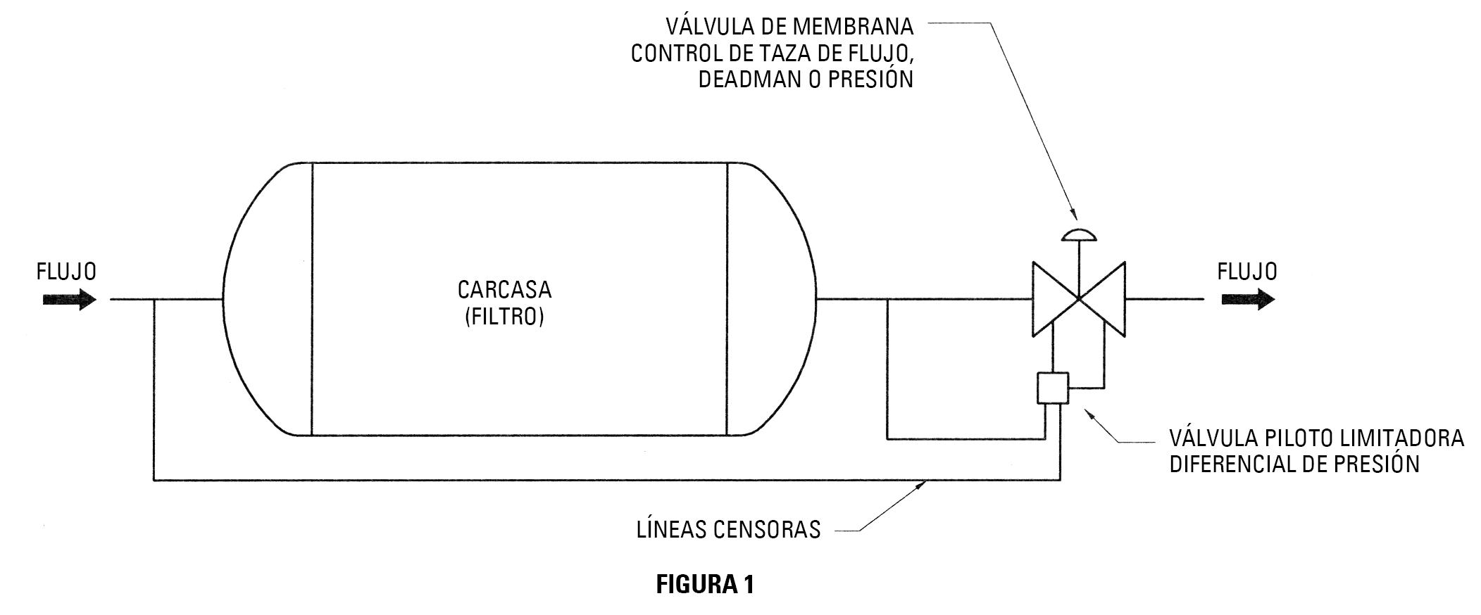
Nuestra intención es que le adiciones un piloto tipo “tasa de flujo” a su válvula de control de membrana; esto se puede hacer aun si ya hay otro igual para controlar el caudal máximo de su filtro, solo que el piloto nuevo no se conecta de la misma manera y debe llamarse “Válvula Piloto Limitadora Diferencial de presión”. Sus líneas censoras no serán conectadas a la placa de orificio en la barra entrada de la válvula (como lo es el piloto de tasa de flujo) pero se conecta desde de la propia carcasa (Consulte la figura 1)

Lo que sucede es que cuando la caída de presión en la carcasa es menor que su punto de ajuste (digamos 15 psid) el piloto no se activa. Sin embargo cuando la caída de presión llega a 15 psid, este piloto cierra la válvula principal lo suficiente para mantener 15 psid. Cuanta más suciedad halla (o agua, en el caso de los monitores), el flujo disminuirá pero nunca excederá los 15 psid, se pierde caudal, pero no se revientan los elementos. En resumen estás haciendo que la válvula de membrana absorba la caída de presión, en vez de los elementos filtrantes.

Nota: En el caso de los elementos monitores (absorbentes) colocados en los carros de hidrantes es más recomendable utilizar el sistema de interruptor ya que la respuesta es mucho más rápida que este sistema, (consulte GamGram 56 y GamGram 65)

La belleza de este sistema consiste en que le permite continuar la operación de manera segura a un caudal más reducido, y con ello extender la vida útil del elemento y se gana tiempo para obtener un nuevo conjunto de elementos. Nótese que ningún otro sistema puede hacer esto, y sorprendentemente, también es la solución menos costosa.

El sistema no solo se aplica a los filtros separadores estacionarios, sino que también funciona en un camión repostador, siempre que haya una válvula de control en línea. Esto es especialmente útil para usar en las carcasas de filtros absorbentes y funciona con válvulas de diafragma y con las del tipo pistón.

Los Gamgram siempre se han escrito para proporcionar información técnica; nunca con el objetivo de hacer propaganda de venta a nuestros productos. No obstante, aunque este se acerca a una acción de marketing, no quiere decir que estamos promocionando nuestro producto Estamos tratando de educar y demostrar las ventajas de este sistema para que sea colocado en todas las carcasas nuevas a instalarse. Esto le garantizara una operación segura para sus instalaciones. Hemos visto el asunto con los fabricantes de estas válvulas y ellos tendrán disponibles kits de actualización. Estaríamos muy felices de no escuchar nunca más casos de elementos filtrantes reventados. Además, puede configurar el piloto de forma segura a 20 o 25 psid o más! Tiene más sentido que 15 psid en recipientes con elementos de otro tipo. ¡Revise las políticas de su empresa antes de cambiar!

GamGram 44: Control de Caída de Presión del Filtro Separador2026-08-27T09:49:08-04:00

GamGram 44: Filter Separator Pressure Drop Control

When I was a boy, I heard a story of an event that happened in a nearby town. A large truck (lorry) got stuck under a low bridge. There was great confusion and no one could figure out how to remove the truck. A young boy kept trying to get a police officer’s attention and the policeman kept telling him to go away. The child was persistent and finally the policeman allowed him to speak his mind. He suggested letting some of the air out of the truck tires and, of course, it worked.

I tell this story because sometimes I feel a bit like that little boy. The message of this GamGram is that there is an inexpensive yet elegant solution to the problem of burst or collapsed elements in filter separator, in regard to water absorbing “monitor” filter, see GamGram 56 and GamGram 65.

The solution which most people think of first is installation of a differential pressure switch. This works fine, but you also need a control system, test/reset button and indicator light. Including installation, this can get expensive. To help keep the cost and complexity down, we offer a prefabricated system and even retro fit kits to allow you to easily install a test switch on our existing Gammon Gauge to automatically stop flow if excessive differential builds up. But when you have a control or slug valve already present, there is a better solution.

There are “slug valves” on the outlet of most filter separators, and pressure control valves on refueler vehicles. These valves stop flow if water collects in the vessel sump. These are controlled by small pilot valves designed to interface with a float control valve on the filter separator vessel. Frequently, pressure or rate of flow pilots are also included on these valves.

The manufacturers of these slug valves make a little known pilot valve (which can be added) called a Differential Control Pilot Valve.

The Differential Control Pilot Valve can sense pressure drop across the filter vessel and stops flow if pressure drop exceeds a set point (for example – 15 psid). This is one solution, but there is an even better and less expensive solution.

DIFFERENTIAL PRESSURE LIMITING PILOT

Our idea is that you add a “rate of flow” type pilot to your slug control valve. You do this even if you already have a rate of flow control pilot. The new control pilot will not be connected the same way and should be called a Differential Limiting Pilot Valve. Its sense lines are not connected to the orifice plate on the slug valve inlet (as the rate of flow pilot is) but are connected across the vessel itself.
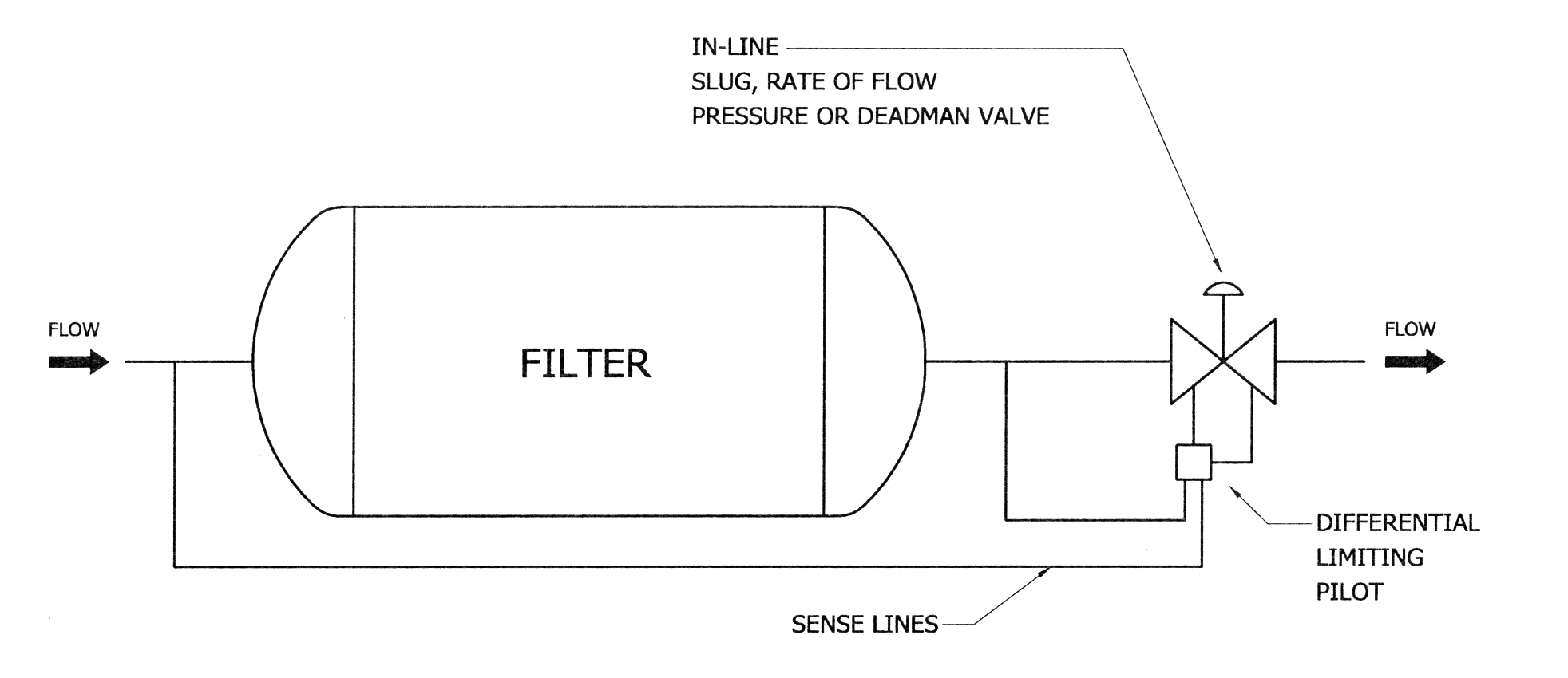
What happens is that when pressure drop is less than your set point (let’s say 15 psid) the pilot does nothing. But when pressure drop reaches 15 psid, this pilot starts to close the main valve just enough to maintain 15 psid. The more dirt (or water, in a vessel with water absorbing elements), the lower the flow rate, but you never exceed 15 psid. You lose flow rate, but don’t burst the elements. Put simply, you are making the slug valve absorb the pressure drop, not the elements. (Note, on water absorbing elements on a hydrant cart in a high pressure hydrant system, it is better to use a pressure switch for faster reaction time, see GamGram 56 and GamGram 65.

The beauty of this system is that it allows you to safely continue operation at a reduced flow rate, extending element life and giving you time to get a new set of elements. No other system can do this, and amazingly, it is also the least expensive solution.

Not only can this system be applied to stationary filter separators, but it will also work on a refueler truck, as long as an in-line control valve is present. This is especially handy for use on vessels with water absorbing elements or modern fuse monitor elements. It will work with diaphragm or piston type valves.

Well now, GamGrams have always been written in a way to provide information, not to make a sales pitch for our products. This GamGram is definitely aimed at selling, but it’s not our product. We are trying to sell you on requesting this feature on all new vessels. It will insure safer operation of your facility. We have spoken to the valve manufacturers and they will have retro-fit kits available. We would be happy to never hear about burst coalescers and/or collapsed elements again. In addition, you could safely set the pilot up to 20 or 25 psid or more! This really makes better sense than 15 psid on water absorbing vessels, especially on hydrant trucks. Velcon, for one, is now recommending a 25 psi change out on fuse type elements. (Check your company policies before changing!)

GamGram 44: Filter Separator Pressure Drop Control2026-05-28T10:56:24-04:00
Go to Top